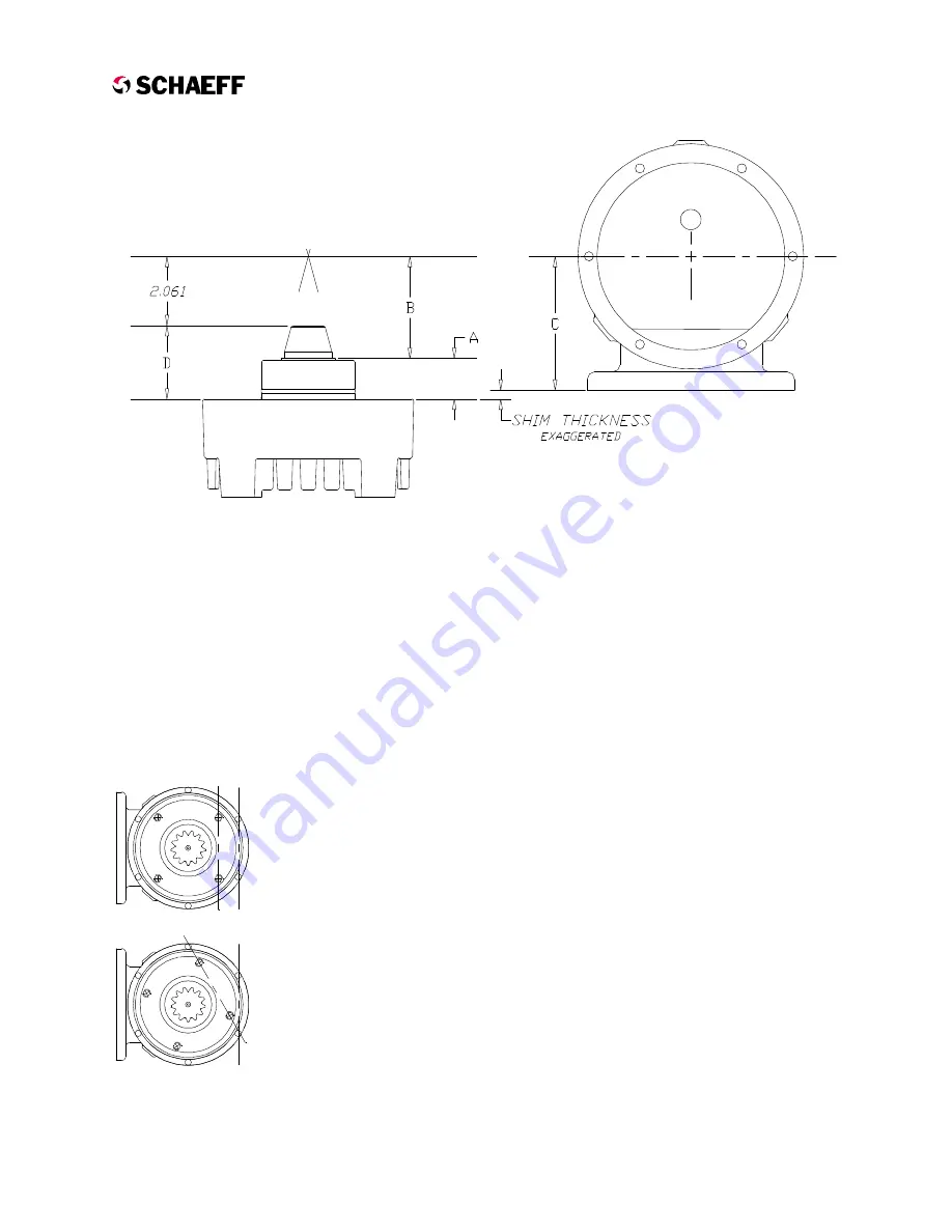
Example for
Procedure 1
:
Measurement
A
= 1.394
Etched on Pinion
B
= 3.240
Stamped on Gearbox
C
= 4.611
1.394 + 3.240 - 4.611 = 0.023
4-Hole
Shim Package = 0.023"
Example for
Procedure 2
:
Measurement
D
= 2.573
Add 2.061
Stamped on Gearbox
C
= 4.611
2.573 + 2.061 - 4.611 = 0.023
4-Hole Shim Package = 0.023
2.
Assemble a 4-hole shim package as
determined in Step 1 (verify thickness with a
micrometer) and install on the motor mounting
face.
3.
Remove the carrier assembly from the gear
housing. Apply a thin coat of grease to the
outer diameter of the motor pilot flange and
secure the gear housing to the motor using
four 3/8-16 nylon lock nuts (torqued to 30 lb-ft)
as either a left or right drive unit as required.
Carrier to Gear Housing Assembly
1.
Place a 6-hole shim package (Fig. 2.6, Item
18) over mounting flange on gear housing.
Initially use 0.022” or the same thickness that
was removed during disassembly.
2.
Coat an approximately 30
o
area of the ring
gear with marking compound for checking the
tooth contact pattern.
E
lectric
C
ounterbalance
H
igh
O
utput
Drive
12/20/99
2.9
Figure 2.10 - Carrier to Housing Alignment
Procedure 2
Measure D if there
is no number on
the end of pinion.
Procedure 1
Measure A if there is
a number on the end
of pinion.
Figure 2.9 - CALCULATE 4-HOLE SHIM THICKNESS.
Correct
alignment
Incorrect
alignment


