Document type
Document number
Rev
Page
Manual
66024
C
18 of 37
3.5.3
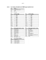
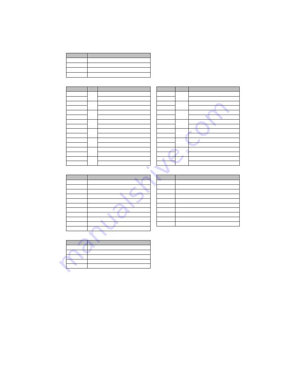
Terminal schematics for PWM type Central Unit
K7
Main
Pin no.
Description
K7.1
Supply (+12/24 VDC)
K7.2
GND
K7.3
DV +
K7.4
DV GND
K1
Analog outputs
K3
Analog outputs
Pin no.
No. Description
Pin no.
No.
Description
K1.1
PWM +
K3.1
PWM +
K1.2
1A
GND
K3.2
5A
GND
K1.3
PWM +
K3.3
PWM +
K1.4
1B GND
K3.4
5B
GND
K1.5
PWM +
K3.5
PWM +
K1.6
2A
GND
K3.6
6A
GND
K1.7
PWM +
K3.7
PWM +
K1.8
2B GND
K3.8
6B
GND
K1.9
PWM +
K3.9
PWM +
K1.10
3A
GND
K3.10
7A
GND
K1.11
PWM +
K3.11
PWM +
K1.12
3B GND
K3.12
7B
GND
K1.13
PWM +
K3.13
PWM +
K1.14
4A
GND
K3.14
8A
GND
K1.15
PWM +
K3.15
PWM +
K1.16
4B GND
K3.16
8B
GND
K4
EX1 - Digital outputs / inputs
K6
EX2 - Digital outputs / inputs
Pin no.
Description
Pin no.
Description
K4.1
Digital output 1
K6.1
On / Signal
K4.2
Digital output 2
K6.2
Digital output 7
K4.3
Digital output 3
K6.3
Digital output 8
K4.4
Digital output 4
K6.4
Digital output 9
K4.5
Digital output 5
K6.5
GND
K4.6
Digital output 6
K6.6
Digital output 10
K4.7
GND
K6.7
Digital output 11
K4.8
Digital input 1
K6.8
Digital output 12 / Digital input 4
K4.9
Digital input 2
K6.9
Digital output 13
K4.10
Digital input 3
K6.10
GND
K4.11
Input supply (+VDC)
K8
EX3 - Optional features
Pin no.
Description
K8.1
Customer specific
K8.2
Customer specific
K8.3
Customer specific
K8.4
Customer specific
K8.5
Customer specific
18/37
Summary of Contents for RC400
Page 1: ...Instruction Manual RemoteControlSystemRC400 Document 66024 Revision D Language English ...
Page 2: ......
Page 39: ......
Page 40: ......


