


8
●
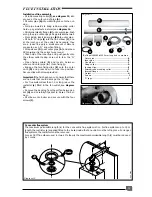
Copper tubing or plastic Hep
2
0 may be used for
the domestic hot water system. Unnecessary
pressure losses should be avoided.
●
A flow restrictor limiting the flow through the boiler
to a maximum of 16 l/min is fitted to the boiler.
●
The boiler will operate with a minimum supply
pressure of 0,7 bar, but under reduced flow rate.
Best operating comfort will be obtained from a sup-
ply pressure of 1 bar.
DOMESTIC HOT WATER SYSTEM DESIGN
'Hard Water Areas'
In areas where the water is 'hard', more than
200mg/litre, it is recommended that a proprietary
scale reducer is fitted in the cold water supply to
the boiler.
Shy 163cUK
Diagram 6
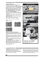
BOILER SCHEMATIC
1
-
Domestic thermistor
2
-
Three way valve
3
-
Gas valve
4
-
Gas valve ignition module
5
-
Temperatur sensor for accumulation vessel
6
-
Accumulation vessel
7
-
Burner
8
-
Ignition electrode
9
-
Combustion chamber
10 -
Heating safety valve (3 bar)
11 -
Main heat exchanger
12 -
Air pressure switch
13 -
Flow detector
14 -
DHW pump
15 -
Non return valve
16 -
Bypass
17 -
Domestic heat exchanger
18 -
Heating pump
19 -
Heating expansion vessel
20 -
Heating thermistor
21 -
Overheat safety thermostat
22 -
Flame sensor electrode
23 -
Fan
24 -
Domestic safety valve (6 bar)
25 -
Loss of water sensor
26 -
Domestic expansion vessel
27 -
Pressure/temperature relief (7 bar)
28 -
Domestic safety valve (10 bar)
A
-
Heating return
B
-
Cold water inlet
C
-
Heating flow
D
-
Domestic hot water outlet
E
-
Gas
D1 -
Discharge from HTG safety valves
D2 -
Discharge from DHW safety valves
D3 -
Discharge from temp/press (to tundish)
A
B
C
D E
D1
D1
D1
D2
D1
D3
2
3
6
4
26
7
5
8
9
1
12
13
10
28
15
14
16
18
17
19
20
22
21
23
11
25
24
27
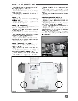
D1
D3
Discharge from HTG+
domestic prv on jig
D2
Discharge from DHW
safety valves
Tundish
Gully
Diagram 6a
Valve
outlet size
Maximum
resistance
allowed
expressed as a
length of
straight pipe
i.e. no elbows
or bends
Resistance
created by
each elbow or
bend
Minimum
size of
discharge
pipe D2
from
tundish
Minimum
size of
discharge
to tundish
G 1/2
15 mm
22mm
up to 9 m
0.8 m
28 mm
up to 18 m
1.0 m
35 mm
up to 27 m
1.4 m
G 3/4
22 mm
28 mm
up to 9 m
1.0 m
35 mm
up to 18 m
1.4 m
42 mm
up to 27 m
1.7 m
G 1
28 mm
35 mm
up to 9 m
1.4 m
42 mm
up to 18 m
1.7 m
54 mm
up to 27 m
2.3 m


