


10
PIPING SYSTEM INSTALLATION
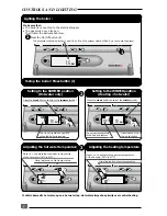
Step. 1
The internal safety valves have been tee'd together
and the discharge pipe run so that it exits at the
right hand bottom of the boiler (
diagram 6
) (
D2
).
The tundish (supplied) must be used with this outlet
within the normal guidelines and code of practice
(
diagram 6a
).
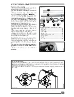
Step 2
Tee the domestic safety valve (
diagram 7
) (
28
)
outlet to the heating safety valve (
10
) outlet
together. You can either extend this pipe
horizontally to the outside wall. WARNING, It must
not discharge above an entrance or window or
any type of public access area, the discharge must
be extend using no less than 15 mm o.d. pipe to
discharge in a visible position outside the building,
facing downard preferably over a drain. The pipe
must have a continuous fall and be routed to a
position so that any discharge of water, possibly
steam, cannot create any danger to persons,
damage to property or exter nal electrical
components and wiring.
alternatively : The discharge pipe can be tee'd into
the other discharge pipe after the tundish (
diagram
6
) provided that it has a continuous fall and that
provisions are made for the size of discharge pipe
immediately after the tundish (
see diagram 6a
)
.
Safety valve discharge
Domestic hot water supply options
Under normal circumstances, the domestic hot
water storage temperature inside the boiler can
be stored between 37 and 60
°
C. It is
recommended that the boiler storage temperature
is set by the user to the maximum of 60
°
C - this will
ensure a more plentiful supply of hot water.
It may be desirable to provide hot water to
separate outlets at different temperatures (for
example, to provide a limited temperature to
prevent the risk of scalding). To be able to do this,
a thermostatic mixing valve is supplied with the
Isomax boiler (factory set to 43
°
C) and can be fitted
during the installation procedure.
There are 2 options for the domestic hot water
supply :
1 -
Piping the hot water supply without the use of
the mixing valve to provide hot water to all taps at
the same temperature.
2 -
Piping the hot water supply using the mixing
valve (supplied) to provide hot water at boiler hot
water “set temperature” to one tap and
thermostatically controlled hot water to another
tap(s).
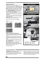
To pipe the hot water supply using the mixing valve,
refer to
diagram 8
. This shows one outlet supplying
hot water at the boiler hot water "set temperature"
and one hot water outlet at a temperature pre-set
at the mixing valve. The mixing valve can be set
between 35 and 60
°
C. It is recommended that the
valve is adjusted (and locked) by the installer to
the desired temperature.
The connections to the mixing valve are :
H
- Hot water supply from boiler
C
- Reduced cold water supply
MIX
- Thermostatically controlled outlet
Warning :
It is strongly recommended that the cold
water supply to the mixing valve is taken from the
reduced side of the pressure reducing valve
(supplied)
Note 1 :
The mixing valve is fitted with two in-line
strainer, one on the hot inlet and one on the cold
inlet. For servicing details of these, refer to the
separate instructions supplied with the mixing valve.
Note 2 :
The mixing valve incorporates a "rapid
failsafe" device which will automatically close the
valve to safety in the event of supply failure on
either hot or cold water.
The discharge must be extended using not less than
22 m o.d. pipe, to discharge in a visible position
outside the building, facing downward preferably
over a drain.
The pipe must have a continuous fall and be routed
to a position so that any discharge of water, possi-
bly boiling or steam, cannot create any danger to
persons, damage to property or external electri-
cal components and wiring. Tighten all pipe con-
nection joints.
Gas connection
●
The supply from the governed gas meter must be
of adequate size to provide a constant inlet work-
ing pressure of 20 mbar (8 in w.g.).
To avoid low gas pressure problems, it is recom-
mended that the gas supply is connected using 22
mm pipe.
●
On completion, the gas installation must be
tested using the pressure drop method and purged
in accordance with the current issue of BS6891.
Gas Safety (Installation and use) Regulations
In your interests and that of gas safety, it is the law
that ALL gas appliances are installed and serviced
by a qualified registered person in accordance with
the above regulations.


