


12
e
e
a
a
X
X
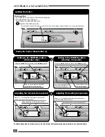
BOILER INSTALLATION
Statutory requirements
The installation of this boiler must be carried out by
a qualified registered person in accordance with
the relevant requirements of the current issue of:
The Gas Safety (Installation and Use) Regulations
The Building Regulations
The local water company Byelaws
The Building Standards Regulations (Scotland)
The Health and Safety at Work Act
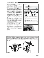
Sheet metal parts
WARNING. When installing or servicing this boiler,
care should be taken when handling the edges of
sheet metal parts to avoid the possibility of personal
injury.
Installing the boiler
Prior to starting work, the system must be thoroughly
flushed using a propriety cleanser such as
Sentinel
X300
to eliminate any foreign matter and contami-
nation e.g. metal filings, solder particles, oil, grease
etc.
Note
. Solvent products could cause damage to the
system.
●
Engage boiler upper part onto the hanging
bracket.
●
Fit the washers between the boiler pipes and the
inlet and outlet fittings on the fixing jig and con-
nect the various couplings between the boiler and
jig.
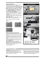
FLUE INSTALLATION
Top outlet flue - kit 85090
The boiler is only suitable for top outlet flue
connection.
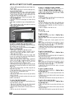
Rear flue systems
The calculate the lenght when flueing to the rear
measure
e (diagram 11)
plus 25 mm outer flue pipe
and
e
plus 125 mm to inner pipe measurement.
Calculation of cutting lengths when flueing to the
right or left
●
Measure wall thickness
e
(mm),
see diagram 11.
For right hand applications
●
Measure distance from inside face of wall to side
of the boiler
a (diagram 11)
add 350 mm to outer
pipe measurement and 445 mm to inner pipe
mesurement.
For left hand applications
●
Measure distance from inside face of wall to side
of the boiler
a (diagram 11)
subtract 25 mm for
outer pipe length and add 75 mm to inner pipe
length measurement.
●
Refer to
table 2
for cutting lengths of both inner
and outer flue pipes for each of the various flue
options available.
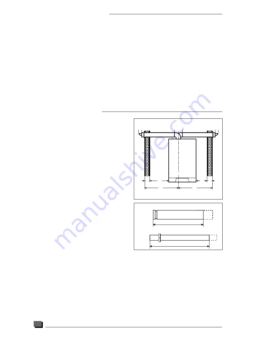
Important
: All flue cutting lengths must be meas-
ured from the terminal end of the flue pipes,
see
diagram 12.
When the dimension
X
measured on site is greater
than that given in
table 2
. Extensions will be required
as necessary.
Important:
All cutting lengths should be measured
from the push fit joint end of the extension pipe.
Do not leave any burrs or sharp edges on the cut
ends of the pipes.
Note :
maximum horizontal flue lenght without
bends is 3 m.
Table 2
Flue cutting lengths (mm)
Rear flue
Outer pipe : e + 25,
inner pipe : e + 120
Comment : maximum distance 'x' without extension 770 mm
Right side flue
Outer pipe : e + a + 350, inner pipe : e + a + 450
Comment : maximum distance 'x' without extension 515 mm
Left side flue
Outer pipe : e - 25,
inner pipe : e + 125
Comment :
maximum distance 'x' without extension 1087 mm
Hab 210a
Diagram 11
V
en 089
Diagram 12
Cutting length
Outer pipe
Inner pipe
Cutting length


