


30
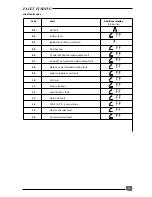
FAULT FINDING
Before trying to operate the boiler make sure that :
• All gas supply cocks are open and that the gas
supply has been purged of air.
• The heating system pressure is at least 1 bar.
• There is a permanent mains supply to the boiler.
• The fuse on the PCB is intact.
WARNING.
Always isolate the boiler from the elec-
trical supply before carrying out any electrical re-
placement work.
Always check for gas soundness after any service
work.
Should there be any doubt about the voltage sup-
ply to any of the components, it is possible to carry
out a simple electrical test to ensure all is opera-
tional in that area.
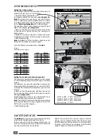
To carry out the electrical test, gain access to the
main Printed Circuit Board (PCB), as described pre-
viously, and measure the voltages according to
table 1.
The
ISOFAST
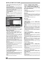
has an on-board fault diagnostic system. Should a fault occur on the boiler, the warning LED at
the top of the user display
will illuminate and the LCD display will indicate the precise area where the
fault has occured.
Table 1
Voltage
Measured value
Measuring point
230 Volt
230 V AC
Between terminals H8.1 and H8.2
24 Volt
maximum 33V DC
Between terminals B2.4 and B2.7
minimum 20V DC
15 Volt
15V
+ 0.5V
Between terminals B2.4 and B2.2
Display
5V
+ 0.5V
Between terminals B2.4 and B4.2
09
FF
Sec 052
A fault code is displayed on the left hand side of the LCD display, whilst at the same time, the letters
FF
appear with a telephone symbol.


