


18
COMMISSIONING
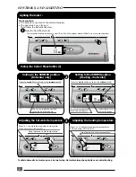
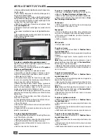
Setting the heating output
The heating output can be set without the use of a
pressure gauge; proceed as follows:
●
Press the display light button
and keep pressed for 5 seconds,
see diagram 20.
Note
:The boiler has now been put into 'Service
Mode', allowing certain adjustments to be made
and diagnostic fault codes to be displayed. Refer
to the
'Servicing Instructions'
for further details.
The heating output, in kW, is shown on the left hand
side of the display,
see diagram 21.
●
Remove the blanking plug from the front of the
control panel to gain access to the heating ad-
justing screw.
●
Adjust the heating output by turning the screw
clockwise to increase, anti-clockwise to decrease.
●
Refit blanking plug.
Note:
Adjustment of the heating output does not
affect the domestic hot water output.
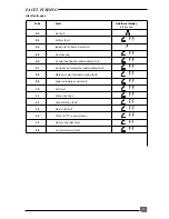
For kW to Btu/hr conversion refer to
table 5.
Setting the heating output
20
01
5 s
1
2
mode
Reg 051/UK
Setting the heating output
Reg 052
Adjustment screw
The heating output, in kW,
is shown on the display.
Diagram 21
Diagram 22
Diagram 20
Table 5
kW to Btu/hr conversion
kW
Btu/hr
10
34,120
12
40,940
14
47,770
16
54,590
18
61,420
kW
Btu/hr
20
68,240
22
75,060
24
81,890
26
88,710
28
95,540
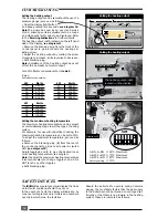
Setting the maximum heating temperature
The maximum heating temperature can be preset
at commissioning stage to suit the type of heating
system.
For example, for use with underfloor heating, the
maximum heating temperature can be set to 53
°
C.
To adjust the maximum temperature, proceed as
follows:
Remove the blanking plug (
b
) from the rear of
the control panel to gain acess to selector switch
SW1 (
see diagram 22
).
Adjust toggles
1
and
2
to give the desired maxi-
mum heating temperature, see diagram
Note:
To adjust the maximum heating temperature
it is only necessary to change toggles 1 and 2. Do
NOT touch any other toggles.
Refit blanking plug.
b
➦
Reg 053
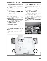
SAFETY DEVICES
The
ISOMAX
incorporates a visual display that indi-
cates fault conditions, should they occur.
In the event of a fault, the display will indicate, by
means of pictograms and/or letters and numbers,
exactly in which area the fault lies.
Should the boiler fail to operate during Commis-
sioning, the most likely fault is that the gas supply
to the boiler has not been turned on or purged suf-
ficiently or that there is no pressure in the heating
system. These are indicated as follows :
1
2 3 4 5 6 7
O
N
SW1
1=ON, 2=ON
➜
53
°
C. Maximum.
1=OFF, 2=OFF
➜
73
°
C. Maximum.
1=OFF, 2=ON
➜
87
°
C. Maximum.
Factory setting
➜
73
°
C.
kW
Btu/hr
30
102,360
32
109,180
34
116,000
35
119,420


