background image


- 24 - 

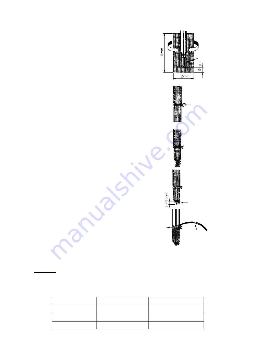
3.  Cut a piece of gauze large enough to fit around the bulb 

(100 x 25 mm), and dampen it with distilled water. Extend 
the gauze about 10mm from the end of the bulb, and wind 
the gauze around the sensing part without making wrinkles. 


4.  Use cotton thread to tie the gauze firmly around the 

sensing part. 

      (about 30mm from the tip of the bulb)   


5. Tie of the end of the gauze with another piece  of tread. The knot 

should be snug. 


6.  Cut  off  the  gauze  about  2  or  3  mm  beyond  the  end  of  the 

sensing part. 


7.  Carefully  pull  out  and  remove  the  horizontal  threads 

(woofs)  of  gauze  above  the  hollow  of  the  sensing  part, 
leaving only the vertical strands (warps). Make a string by 
binding the remaining wraps of gauze. 


8.  Put back the lower part of air intake tube, clamp, and insert the string into the water reservoir. 

Follow steps 4, 5, 

6 in “Replacing the wick”. 


Cautions 

● 

On interval of water supply 

Duration of continuous operation with a supply of water differs depending on the circumstances 
where  the  instrument  is  used.  Be  careful  about  water  level  of  feed  water  tank  referring  to  the 
following table 1.      Refer to the following chart just for a rough standard.


Lower than 40%rh   

  Higher than 40%rh 

Lower than 15


about 20 hours 

about 30 hours 

15 to 35


about 25 hours 

about 35 hours 

35 to 50


about 15 hours 

about 20 hours 

Tie  off  the  end 
of the gauze 

Cut off the 
gauze 

Make a string by 
binding the 
remaining warps 

Knot 
above 
bulb 

Bul

Use cotton thread 
to the gauze 
firmly 

Summary of Contents for 7435-50

Page 1: ...Instruction Manual No 7435 50 Multiple Measuring System Model SK 5RAD MR 3 4 Kanda kajicho Chiyoda ku Tokyo 101 0045 Japan URL http www sksato co jp english P 12...

Page 2: ...ipment in an area subject to dust flammable gas explosive gas corrosive gas SO2 H2S etc etc Using this equipment in an environment with electrical noise may produce an unstable display or an increase...

Page 3: ...supply voltage of this equipment 1 Power supply rating 100 to 240 VAC 50 60 Hz 25 VA max 2 Operating voltage range 85 to 264 VAC Note The power cord provided is exclusively used for 100 VAC If the equ...

Page 4: ...ames product names system names etc are trademarks or registered trademarks of their respective companies Overview The operating principle of this equipment is based on the wet and dry bulb system whi...

Page 5: ...s must specify this option when placing an order Components Sensor Hanging ring Used to suspend the sensor Wall mounting bracket Used to mount the sensor on a wall Power switch Turns the DC motor on a...

Page 6: ...toward you while pushing the two knobs downward To close the cover push it straight back in place while holding down the knobs Terminal block Used to connect the power cord and sensor cable LAN conne...

Page 7: ...11 12 13 14 15 16 17 18 19 Dry bulb temperature CH1 Wet bulb temperature CH2 A B B A B B Wire color R terminal color Red Red White Red Black Red Orange Blue Blue Blue Brown Blue Note For brushless mot...

Page 8: ...en installing the sensor on a wall use the appropriate screws for the installing location The sensor can also be hanged by using the hook on the sensor head A tripod for hanging the sensor is optional...

Page 9: ...ile phones Level places forward tilt 0 backward tilt between 0 and 30 Water supply method Caution When handling the string of wick use a pair of tweezers or wash your hands with soap to prevent the tr...

Page 10: ...quipment was purchased or our service network If measured values are abnormal such as measured value exceeds the measuring range or the dry bulb temperature is lower than the wet bulb temperature B OU...

Page 11: ...d the SD memory mark is lit in red in the memory status display section During this state never remove the card Doing so may damage the data and cause the equipment to fail You can freely change the r...

Page 12: ...OM provided Installation Turn off any active applications currently running before installing this software If the previous version has been installed delete the software using Add Remove Programs in...

Page 13: ...s optional functions however these cannot be used The Engineering key on the menu screen is used for the factory adjustment only Do not change the settings for these functions Note that any loss of or...

Page 14: ...d In this state never remove the SD memory card MiniSD and MicroSD memory cards cannot be used If an adapter for MiniSD or MicroSD is used for these cards there is a risk of not being able to remove t...

Page 15: ...ouching this area enables the screen title to be changed Time display This area displays the current date and time Trend changeover This area is used to switch the type of trend screen REAL or HIST No...

Page 16: ...D memory card is mounted or an SD memory card that is mounted can be removed Light blue An SD memory card has been mounted Red The equipment is communicating with the SD memory card Data is being writ...

Page 17: ...ry overwriting OFF Data is not overwritten when the SD memory card becomes full Storage format CSV data and binary data Recording type Instantaneous value Graph display Digital FUNC button Screen swit...

Page 18: ...CH13 and dew point temperature CH14 Setting Main Touch this button to set up recording Items such as the recording interval can be set here LCD Touch this button to set the screen brightness and auto...

Page 19: ...lly created when an SD memory card is mounted on this equipment To load the stored settings into the equipment touch Param load Selecting the desired settings from all the stored settings loads the se...

Page 20: ...e Set the interval for recording measurements to a file The selectable range varies according to the specified value in Record Cycle File overwrite Select to overwrite data or not when the SD memory c...

Page 21: ...interval is one second the maximum and minimum values of 10 values measured at intervals of 100 ms will be recorded OFF Trend data only is recorded on the Trend screen and is not recorded in the SD m...

Page 22: ...erting an SD Memory Card into this equipment automatically creates a folder named Recorder where four subfolders will be created The subfolders are as follows Cap Contains image files bmp that are cap...

Page 23: ...saved and read by this equipment Settings data created with the software provided Parameter Loader must be stored in this folder Data analysis Installing the analysis software Data Viewer from the CD...

Page 24: ...e clamp convex part is placed and aligned with gloves of the upper and lower sections of the air intake tube At that time don t let the string get stuck or caught between the housing and air intake tu...

Page 25: ...al strands warps Make a string by binding the remaining wraps of gauze 8 Put back the lower part of air intake tube clamp and insert the string into the water reservoir Follow steps 4 5 6 in Replacing...

Page 26: ...s of operation If the motor needs to be replaced due to aging contact the store from which the equipment was purchased or our service network For the continuous operation for a long period of time sel...

Page 27: ...y SD memory card SD max 2GB SDHC max 32GB Water resistance JIS C 0920 IP65 Only for the front of the display with the use of packing for the panel mount Power Requirements 100 to 240VAC 10 50 60Hz 25V...

Page 28: ...customer misuse Out of warranty products will be repaired on charge basis Warranty during transportation The warranty during transportation only applies to the products that we arrange the shipment Th...

Reviews: