5
12. Attach the dome/trim ring by lining up the dots on the
box and the trim ring. Push on one side of the trim ring
near the the flat section of the box, then push on the
other side of the trim ring until it snaps into place. Listen
for a distinct click to ensure ring is securely in place. See
Figure 3.
Figure 3
13. Adjust the dome so that the viewing slot is in the proper
position.
14. Replace any previously removed adjacent tiles.
4.2
Hard Ceiling Mounting
Mount the unit in a hard ceiling, e.g. dry wall etc. as follows.
Be sure the ceiling will support the weight of the housing and
camera.
1. Cut a 172 mm (6.75 in) diameter hole in the ceiling. Use
two pencils (or a pencil and a nail) with the template tool
provided to draw the circle.
2. Run the electrical cable into the housing through the con-
duit and the hole in ceiling as required by the applicable
codes.
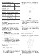
3. Install box into pre-cut hole with the bottom flange press-
ing against the ceiling. Position the round section of the
box in the direction that the camera will be aimed. See
Figure 4.
Figure 4
4. Pull the drawstring tight (away from the screw) and lock
into the groove. DO NOT CUT DRAWSTRING
Push the excess string through the hole provided. As an
option, a screwdriver may be used to turn screws and
lock ceiling clamps in place.
5. Complete the electrical connections.
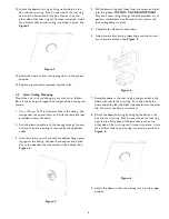
6. Adjust camera bracket to proper angle and mount cam-
era to camera bracket. See Figure 5.
Figure 5
7. Assemble dome in the trim ring by lining the slots in the
dome with tabs in the trim ring. Push one side of the
dome under the tab; the other side should clear the other
tab. Now turn the dome to secure it.
8. Attach the dome/trim ring by lining up the dots on the
box and the trim ring. Push on one side of the trim ring
near the the flat section of the box, then push on the
other side of the trim ring until it snaps into place. Listen
for a distinct click to ensure ring is securely in place. See
Figure 6.
Figure 6
9. Adjust the dome so that the viewing slot is in the proper
position


