background image

30

English

INITIAL SETUP (SETUP WINDOW)

(User Level: ID4)

USER ID tab

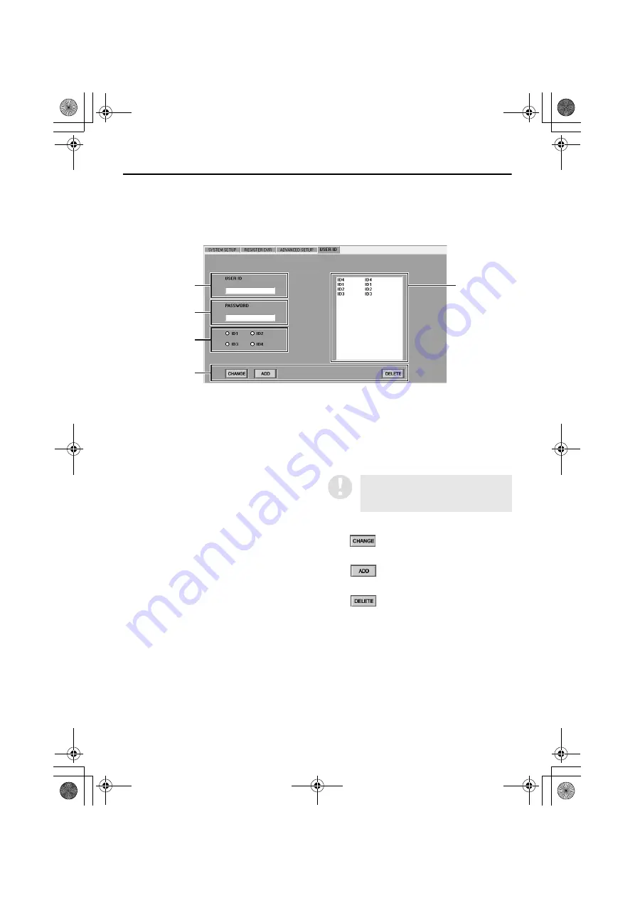
This is used to register, change and delete users who can log into the system. Up to a maximum of 32 
users can be registered.

Names and functions of each window component

1

Username entry box (USER ID)
This sets the username for identifying a user 
on the network.

2

Password entry box (PASSWORD)
This sets the password for authenticating a 
user who is trying to log in.

3

User level setting buttons
These select the user level (operation 
permission level). (P.9)

Available settings: ID1, ID2, ID3, ID4

4

List box
This shows a list of the usernames and user 
levels for registered users.

Select users from this list when carrying out 
operations such as changing and deleting 
user registrations.

5

Operation buttons

Changes the registration details for a user.

Adds a new user registration.

Deletes an existing user registration.

1

4

2

3

5

The default settings for user levels 
ID1 to ID4 are initially displayed in 
the list.

  )-   " #$%&'

Summary of Contents for VA-SW814

Page 1: ...INSTRUCTION MANUAL DVR Utility Software VA SW814 VA SW81LITE ...

Page 2: ...SION SETTINGS BROADCAST WINDOW 52 IMAGE DISPLAY WINDOWS 54 Display Screen Type 54 Switching Display Windows 55 Sequence Display Function 57 Title Bar 58 Zoom Function 59 Full Screen Function 60 MONITORING LIVE IMAGES 61 Monitoring in a QUAD SINGLE Screen 61 Monitoring with MULTI Screens 62 Disconnecting DVRs 63 Image Audio Output 63 RECORDING IMAGES 64 Normal Recording 64 Timer Recording 66 Alarm ...

Page 3: ... monitoring can be switched between a single screen and 4 screen multi screens If a 4 channel DVR is connected images for a maximum of 16 channels can be viewed at once in a single screen The system is provided with complete security features Users that have access to the system are verified by means of a user ID and password and four different user levels ID1 to ID4 are available with different o...

Page 4: ...VRs can be connected depending on the subnet mask values Number of computer terminal connections Max 8 computers 1 master computer 7 slave computers Applicable software If using this software VA SW814 or VA SW81LITE on the master computer then the slave computers must also be running the same version of software Older versions of the software VA SW800 804 814 Ver 1 0 80LITE cannot be used with thi...

Page 5: ...computer terminals that do not have operating privileges for registering and deleting DVRs are called slave computers and a maximum of seven of them can be connected P 20 When using the software on a network carry out the required network settings at the DVRs first IP addresses will be assigned automatically but the DVR NAME and GROUP settings can also be changed manually using a computer P 22 You...

Page 6: ...768 pixel 16 million color or greater 1 AGP graphics card for hardware overlay 2 Sound Sound card that supports 48 kHz stereo playback PCI connection recommended 3 OS Windows XP Professional Recommended graphics chip ATI RADEON9000 series or later nVidia GeForce4 series or later Quadro4 series or later Matrox MillenniumP series or later If the firewall function of Windows XP or some other firewall...

Page 7: ...a Connection Properties window will be displayed 4 Check that Internet Protocol TCP IP is selected in the list of components used by the Ethernet board that appears in the This connection uses the following items O box If Internet Protocol TCP IP is not selected select it 5 Click Properties R The General tab window in the Internet Protocol TCP IP Properties window will be displayed 6 Select Use th...

Page 8: ...ense Agreement carefully 4 Click Next in the Choose Destination Location window Normally you should accept the default location without changing it If you would like to change the destination folder for installing the software type the path to the folder directly into the box or click Browse and select the folder to be used for the installation 5 Click Next in the Select Program Folder window This...

Page 9: ...software Version Updates When updating the DVR Utility Software from version VA SW800 804 to VA SW814 you can follow the procedure given below to reuse the DVR registration list that was created by the VA SW800 804 version 1 Uninstall version VA SW800 804 2 Install version VA SW814 3 Display the SETUP window and open the REGISTER DVR tab 4 With the computer connected to the LAN select MANUAL for T...

Page 10: ...m Playback operations m m m Search operations Time date search m m m Alarm search m m m Alarm thumbnail search m m m Saving operations Saving still images m m m Download m m m Timer download m m m Recording operations Normal recording m m Timer recording m m Initial settings Language TV system master computer download operation limit automatic clock adjustment and sequence interval settings m Regi...

Page 11: ... into the USER NAME box and type the password for verification into the PASSWORD box Then click OK or press the ENTER key If the number entered does not satisfy the checksum conditions the input dialog box will be displayed again If an incorrect serial number is typed in three times in succession AUTHENTICATION ERROR will be displayed and the only available operation will be to exit log off The se...

Page 12: ...play language setting to the required language Available languages English French Spanish German Chinese After you have changed the setting restart the application The displays will then appear in the newly selected language Display While Communication is in Progress When a screen operation has been carried out that requires the system to wait for a response from the DVR the following message box ...

Page 13: ... window MENU window INDIVIDUAL CAMERA window DSR M804 M814 only QUAD SINGLE window ALARM SEARCH window BROADCAST window TIMER DOWNLOAD window SETUP window Download window C P 18 A P 16 TAMPER DETECTION window MULTI window SEQUENCE window DSR M804 M814 only Click to exit the software and close the program window If the hardware key is not installed control buttons marked with will not be displayed ...

Page 14: ...lick Click the required icon to use a function or window CLOCK SYSTEM P 17 34 This displays the CLOCK SYSTEM window Used for clock setting firmware updating and checking system related information MENU P 18 39 This displays the MENU window This window is used to carry out menu settings such as setting recording parameters INDIVIDUAL CAMERA P 54 If the DVR is a DSR M804 M814 4 channel type images f...

Page 15: ...images TAMPER DETECTION P 89 This displays the TAMPER DETECTION window This window lets you determine if any tampering has been carried out on recorded images SETUP P 16 20 This displays the SETUP window This window is used to make initial program settings after the software has been installed 2 EXIT Click to exit the software and close the program window 3 Date and time display This shows the dat...

Page 16: ...te and time that they were recorded I Browse Click this button to specify files that are saved on a computer drive Folders and files can be viewed in a list and you can specify a file by typing its filename into the window The only types of file that can be viewed are files in MP2 format that have been downloaded from a DSR M800 M804 M810 M814 series Files that have been saved in JPEG format canno...

Page 17: ...P tab Display language setting Setting the TV format NTSC PAL in accordance with the input signals Setting the master computer address Download operation limit level setting Setting the automatic adjustment function for DVR clocks Sequence screen switching interval setting 2 REGISTER DVR tab Operation only possible at master computer The options in this tab let you add and remove DVRs on the netwo...

Page 18: ...VRs 2 SYSTEM UPDATE tab This is used to update the firmware for selected DVRs 3 INFORMATION1 tab This is used to display DVR setting information and information about the hard disk and is also used for hard disk initialization 4 INFORMATION2 tab This shows information such as the DVR usage time power outages and the firmware version With the DSR M810 M814 the recording start and stop times are als...

Page 19: ...GE D S TIME SET tab This is used to make settings such as the display language for the monitor connected to the DVR daylight saving settings and also lets you adjust the time for connected peripheral devices With the DSR M810 the REMOTE SET settings can also be carried out 2 REC MODE SET tab This is used to set the recording conditions for DVRs 3 TIMER REC SET tab This is used to set timer recordi...

Page 20: ...the values in the displayed tab will be returned to the default settings If the tab index has changed to yellow use the CANCEL operation to return it to the normal color Menu setting Saving and loading This loads the current menu data from the selected DVR Menu data can also be loaded by double clicking the DVR name in the TARGET window If the tab index has changed to yellow use the IMPORT operati...

Page 21: ...hinese 2 TV SYSTEM Default setting NTSC This sets the TV format NTSC PAL in accordance with the input signals Select a button and then click OK 3 PC TYPE MASTER CONTROL PC Select the type of computer being used and then click OK Available settings MASTER Master computer This is the computer that has all operation privileges available including registering and deleting DVRs that are connected to th...

Page 22: ...computer s clock Use the button to select ON specify the adjustment interval and then click OK The automatic clock adjustment function will operate each time the specified interval of time has passed Available settings 1 2 3 6 12 24 hours 6 SEQUENCE Default setting 1 When using sequence display DSR M804 M814 only use the spin buttons to set the display time screen switching time for each channel A...

Page 23: ...p folders and the DVRs that are assigned to them If you click the symbol at the left of a group the DVRs that have been registered in the group will be displayed and the will change to a If you click the symbol the list of DVRs will disappear and the symbol will change back to a 4 DVR detail list When you click on a group in the tree list the following details for the DVRs that are assigned to tha...

Page 24: ...r of display in the list You can also carry out this operation by dragging and dropping F Operation buttons This saves the setting details into a file and also applies them to the DVR If clicked before you click OK this discards changes to the setting data and returns the data to how it was before the changes were made This deletes a DVR or group registration If you switch to another screen withou...

Page 25: ...hanged DVR NAME At the time of registration a name consisting of the last digits of the MAC address XX XX XX is assigned as the DVR name This can be changed TYPE IP ADDR MAC ADDR Displayed or set automatically If more than one DVR is being registered repeat the same operations for each DVR 5 Click The buttons will be unlocked 6 Change the DVR name and assigned group The initial DVR name and group ...

Page 26: ...f the connected DVR Refer to the instruction manual for the DVR for details The time required for creating the list is normally about 20 seconds but it may take up to about 80 seconds depending on the subnet mask setting If a group name already exists for a DVR that group name will be retained automatically for the DVR when manual setting is carried out Because of this if a group with the same nam...

Page 27: ...ther DVRs Changing DVR names At the time of registration a name consisting of the last digits of the MAC address XX XX XX is assigned as the DVR name You can change the initial name to some other name by following the procedure below 1 Specify the DVR Click the DVR to be changed in the tree list or in the DVR detail list The entry in the tree list will be highlighted in blue 2 Enter the new DVR na...

Page 28: ...roups and assign them to new groups by dragging and dropping the DVRs from one group to another If a group exists with no DVRs assigned to it no new groups can be registered 4 Click The setting details will be saved in the computer and also applied to the DVRs 1 Specify the group Click the group to be changed in the tree list The entry in the tree list will be highlighted in blue 2 Enter the new g...

Page 29: ...VRs within the group they are assigned to Alternatively you can use drag and drop operations to move the DVRs to any desired position After making any changes click If you select a DVR that is at the top of the list within a group and then click j j j j the assignment for that DVR will be moved up to the group that is above the current group Similarly if you select the DVR that is at the bottom of...

Page 30: ...VRS setting to USE USE Expanded mode When the number of DVRs to be connected is more than 1001 NO USE Default setting When the number of DVRs to be connected is 1000 or less 3 Specify the number of DVRs to be connected When expanded mode USE has been selected the MAX NUMBER OF UNITS setting can be selected The number of DVRs that can be connected in accordance with the subnet mask setting are disp...

Page 31: ...authenticating a user who is trying to log in 3 User level setting buttons These select the user level operation permission level P 9 Available settings ID1 ID2 ID3 ID4 4 List box This shows a list of the usernames and user levels for registered users Select users from this list when carrying out operations such as changing and deleting user registrations 5 Operation buttons Changes the registrati...

Page 32: ...st of from 4 to 16 alphanumeric characters and passwords are case sensitive You can also use the symbols 3 Specify the user level Use the radio buttons to select the operation permission level for the user being registered P 9 Available settings ID1 ID4 4 Click The password verification dialogue box will be displayed 5 Re enter the password Re enter the same password that was entered in the PASSWO...

Page 33: ...ails Follow the same steps as when registering a new user to change the registration details username password or user level 3 Click If the username or user level has been changed The registration will be completed and the list box display will also be updated If the password has been changed The password verification dialogue box will be displayed Re enter the current password in the CURRENT box ...

Page 34: ... 2 Click A delete confirmation dialogue box will be displayed 3 Click Yes The deletion will then be complete and the user registration will also be removed from the list box display The operations in this tab can only be carried out by users who are logged in at user level ID4 but in addition to this adding changing and deleting registrations for ID4 user levels can only be carried out at the mast...

Page 35: ...the selected DVR will change to blue 3 Select the setting mode and then click OK AUTO Default setting The date and time from the computer s internal clock will be automatically applied to the DVR If you would like to set the date and time for all connected DVRs in a single batch operation in AUTO mode use the BROADCAST function P 52 MANUAL If MANUAL is selected as the setting mode the settings in ...

Page 36: ...IN 5 Click OK 3 3 3 3 A dialog box asking you to confirm the update will be displayed Click YES to continue with the update To change the name of the file that has been entered click CANCEL before clicking OK 6 Run the update A dialog box showing the progress of the update will be displayed and the green indicator will flash Only firmware files that have been provided by SANYO can be used for upda...

Page 37: ...U window 4 ALARM COUNT Shows the cumulative number of alarms The maximum number of alarms that can be recorded is 99 999 When the maximum number of alarms is exceeded the counting starts again from 0 Hard disk information and initialization 5 DISK1 Shows the total capacity of the standard hard disk 6 DISK2 Shows the total capacity of the expansion hard disk 7 MIRRORING This displays the mirroring ...

Page 38: ...all images that are stored on that hard disk will be erased You should make a backup of any important data on a separate storage device before carrying out the initialization Refer to the documentation provided with the DVR for details on how to save data If an additional hard disk has been added be sure to initialize it Ask the place of purchase for details on installing an additional hard disk D...

Page 39: ... time for the selected DVR DISK1 USE Total usage time for disk 1 DISK2 USE Total usage time for disk 2 POWER Total power on time for the DVR 3 POWER LOSS This shows the power failure history for the selected DVR LOSS Date and time of most recent failure RECOVER Date and time of most recent restore TOTAL Total number of power outages 4 FIRMWARE VERSION Shows the firmware version for the specified D...

Page 40: ...for more than one tab if desired If you switch to another screen without clicking OK after entering or changing any settings a confirmation dialog box will be displayed Use the buttons in the dialog box to select whether you want to save or apply the changed settings P 23 LANGUAGE D S TIME SET tab Specify the DVR to be set in the DVR list in the TARGET window and then click or double click the DVR...

Page 41: ... for daylight saving time to end f Sets the weekday for daylight saving time to end g Sets the month for daylight saving time to end h Sets the hour for daylight saving time to end To change the default setting use drop down list boxes and spin buttons to change the ON time for switching to daylight saving time and OFF time for daylight saving time to end settings click APPLY and then click OK 3 E...

Page 42: ... and then click OK Available settings SUPER Super high quality 56 recording hours or more SUPER Super high quality 84 recording hours or more HIGH High quality 168 recording hours or more STANDARD Standard quality 336 recording hours or more The possible recording times are for reference only and are based on a 120 GB hard disk Table of picture quality modes 1 2 3 4 5 6 7 8 9 It is recommended tha...

Page 43: ...king However this varies from the normal situation when OVERWRITE is set to ON in that the data is only overwritten once and when the recording area becomes full again recording will stop once more 4 SERIES REC Default setting OFF If the series recording function has been set when more than one DVR is connected recording can continue onto a second or subsequent hard disk when one hard disk becomes...

Page 44: ...onse to motion sensor input ALARM OR SENSOR In response to either an external alarm or motion sensor input ALARM AND SENSOR In response to both an external alarm and motion sensor input occurring at the same time 8 VIDEO LOSS Default setting ON This sets whether a warning is output or not when the image feed is cut off Select ON or OFF click APPLY and then click OK Available settings ON A warning ...

Page 45: ...ecording 3 SET Default setting OFF This sets whether recording is to be carried out or not during the set timer period Available settings ON Timer recording is carried out OFF Timer recording is not carried out If the stop time is set to an earlier time than the start time a T symbol will be displayed and the stop time will be set to the following day This operation makes it possible to set contin...

Page 46: ...wo rows row 7 and row 8 to make the settings 2 Select MON from the WEEK drop down list box in row 7 3 In the same way use the START spin button in row 7 to select 10 30 4 Select WED from the WEEK drop down list box in row 8 5 In the same way use the STOP spin button in row 8 to select 20 30 6 Select ON in the SET box in row 8 7 After making the above settings click APPLY and then click OK This com...

Page 47: ...hen follow the instructions that appear in the dialog box message to select the setting The data will be loaded from the DVR and the window will become active 1 Click on the DVR to be set in the TARGET window to select it The display color for the selected DVR will change to blue 2 Use the MONTH and DAY spin buttons to set the month and day Up to 20 days can be specified as holidays 3 Click APPLY ...

Page 48: ...if you do not need the information to be displayed click APPLY and then click OK DATE TIME Default setting ON For live images Current date and time For playback images Recording date and time QUALITY AUDIO Default setting ON Image quality and audio recording settings If AUDIO RECORDING is set to ON an A symbol is displayed in the monitor screen ALARM COUNT Default setting ON Cumulative number of a...

Page 49: ... available in a recording area drops to the warning level Only enabled when OVERWRITE is set to OFF KEY IN Default setting OFF When a button on the DVR s front panel is pressed WARNING Default setting ON When one of the following situations occurs When a problem occurs with the hard disk When there is a problem with a fan When an error occurs during recording NON REC Default setting OFF When recor...

Page 50: ...2 DISPLAY Default setting QUAD Select the display window to use when an alarm occurs click APPLY and then click OK Available settings FULL Only the channel where the alarm occurs is displayed in a full window QUAD A 4 screen quad screen is displayed including the channel where the alarm occurred 3 ALARM PRIORITY Default setting LAST This sets the screen display order if multiple alarms occur at mo...

Page 51: ...ndow so that images from specified channels are not displayed Set the window display to ON or OFF for each channel CH1 to CH4 click APPLY and then click OK ON Images and audio are masked The word MASK will be displayed on a black window OFF Images and audio are not masked Refer to page 19 for explanations of the setting buttons CANCEL APPLY ...

Page 52: ...u click a live image from the specified DVR will be displayed in the preview window as a still image Click on one of the squares in the 5 width 4 height matrix in the center of the window The sensor setting will alternate between ON and OFF each time you click Background Sensor ON No background Sensor OFF Sensitivity Default value OFF Select the sensitivity from the drop down list box Available se...

Page 53: ...N OFF commands for the timer button 3 MENU UPLOAD User Level ID4 This broadcasts menu setting data that is stored on the computer s hard disk data that has been saved using the SAVE command to all connected DVRs 1 Click A dialog box will be displayed 2 Select the required menu file that has been saved and then click Open The selected filename will be displayed in the FILENAME box of the MENU UPLOA...

Page 54: ...f the SYSTEM UPDATE window 3 Click The firmware data will then be transmitted Only firmware files that have been provided by SANYO can be used for updates No other files can be used Do not use any file that has not been provided by SANYO to update the DVR s firmware otherwise damage to the DVR may result DVRs cannot be updated while recording or playback is in progress or while the SEARCH menu is ...

Page 55: ...t are connected to the network can all be viewed at once in a 4 screen split screen If all of the assigned DVRs are DSR M804 M814 types 4 channel type then the total number of screens in the multi screen is 16 4 channels x 4 screens 3 INDIVIDUAL CAMERA screen For the DSR M804 M814 this lets you view the camera images in a single screen from one selected camera channel channel 1 to channel 4 from t...

Page 56: ...3 QUAD screen INDIVIDUAL CAMERA screen Click the channel number that you would like to view in the individual camera screen from on the toolbar 4 INDIVIDUAL CAMERA screen QUAD screen Click on the toolbar 5 MULTI screen INDIVIDUAL CAMERA screen Click the title bar to specify a DVR and then click the channel number that you would like to view in the individual camera screen from the on the toolbar 6...

Page 57: ...n Click on the toolbar Or double click the single screen 2 MULTI screen SINGLE screen Click the title bar to specify a DVR and then click on the toolbar Or double click the DVR images that you would like to view in the multi screen SINGLE screen MULTI screen 1 2 DVR 1 CH1 only DVR 1 CH1 only ...

Page 58: ...al camera screen 2 Click on the toolbar The screen will change to the individual camera screen and the images from each channel of the DVR will be displayed continuously in order of channel numbers 3 To stop sequence display Click once more Sequence display will stop and the screen that was displayed before sequence display started quad or individual camera screen will be displayed The display int...

Page 59: ... LIVE Live images being monitored PLAY Playback images playback speed Display example PLAY 1 2 STILL Still image Image date and time In live mode Current date and time In play mode Recording date and time Channel number Camera title Screen select function When viewing live images or carrying out operations such as recording playback or in the multi screen click the title bar to select a window DVR...

Page 60: ...ing on the type of display screen Quad Multi screen Normal 2 4 8 12 Single screen Normal 2 4 6 If you click 2 on the control panel the mode will switch to zoom out mode and the zoom ratio will drop progressively back to normal mode each time you click 3 To return to normal mode Click a screen select button on the toolbar to move to the selected screen The zoom ratio will return to normal at this t...

Page 61: ...n to normal mode Zoom operations in full screen mode If you left click on the point in the image to be enlarged the image will be enlarged centering around that point in steps each time you click The zoom ratios change depending on the type of display screen Quad screen Normal 2 4 8 12 Normal Single screen Normal 2 4 6 Normal Right click twice on the screen in zoom mode or press Ctrl F twice to re...

Page 62: ...een will be displayed 2 Double click a DVR in the TARGET window 2 2 2 2 Live images from the specified DVR will be displayed in a quad screen or single screen depending on the number of channels The title bar will show the DVR name the image mode and the current date and time Display example DVR 1 LIVE 01 20 04 12 13 45 3 To switch the display screen You can switch to a specified screen by clickin...

Page 63: ...3 3 3 3 Live images for the specified DVR are displayed The DVR name image mode and the current time will be displayed in the title bar Display example DVR 1 LIVE 01 20 12 14 15 4 Set the DVR to monitor in the four screens by the same procedure For the DSR M804 M814 the images from a single DVR have a 4 channel structure and so up to a maximum of 16 screens will be displayed 5 To switch the displa...

Page 64: ...for the images being monitored can also be output The sound that is output will come from the DVR that has been specified by clicking a title bar The audio output can be set and adjusted using the audio adjustment panel 1 Volume adjustment Drag the control to the left or right to adjust the volume 2 Output channel selection Use the check boxes to select the channel Multiple channels can be selecte...

Page 65: ... image mode LIVE will be displayed 3 Click 3 3 3 3 on the recording control panel The REC indicator on the DVR will illuminate and recording of the live images will start A b symbol will appear in the title bar while recording is in progress 4 To stop recording click 4 4 4 4 on the recording control panel The REC indicator on the DVR will switch off and recording will stop Normal recording from th...

Page 66: ... will be displayed in the title bar while recording is in progress 5 Recording in a maximum of four windows is possible using the same procedure 6 To stop recording in a window click the title bar to select the window and then click 5 5 5 5 The REC indicator on the selected DVR will switch off and recording will stop Recording images that are not displayed When normal recording is being carried ou...

Page 67: ...VR will switch to timer recording standby mode When the set time is reached recording will start automatically If timer recording has been set a Ä symbol will be displayed in the title bar of the window 3 To stop timer recording while in timer standby mode click the timer button once more If OLY AL REC ON TMR is selected for ALARM MODE in the REC MODE SET tab window alarm recording will have prior...

Page 68: ...en changed and the display has returned to the camera window For 1 and 2 Alarm input will not be received for a maximum period of 4 seconds but alarm input can be received after that Recording of images as a result of alarm input will not be carried out for a maximum period of 6 seconds 3 Immediately after recording ends Alarm input will not be received for a maximum period of 5 seconds but alarm ...

Page 69: ...to PLAY At the multi screen you can use the same procedure to display recorded images for up to a maximum of four DVRs Images from the same DVR cannot be played back in more than one window 3 Using the playback control panel The playback control panel can be used to carry out playback operations such as still and cue P 69 If you click without specifying a DVR the following pop up menu will be disp...

Page 70: ...n again Slow play button This button can be used to carry out slow playback after playback has been paused The playback speed becomes faster each time the button is clicked Speed increments 1 8 1 4 1 2 Notes on starting playback If playback is interrupted and then resumed using the computer playback will resume from the point where it was previously stopped The DVR will be reset once the software ...

Page 71: ...he DVR to be searched The window can be either in the quad screen or the multi screen If using the multi screen click the title bar to specify the DVR to be searched 2 Click the top SEARCH spin buttons 1 1 1 1 to select the date day month year to start searching from 3 Click the bottom SEARCH spin buttons 2 2 2 2 to select the time hour minutes seconds to start searching from 4 Click 3 3 3 3 The i...

Page 72: ... box 3 Display the alarm list The alarm recordings will be displayed in the alarm list window 4 in order starting from the latest recordings If the specified DVR is a DSR M804 M814 you can click the tab index at the top of the list to display a list for only the specified channel channel 1 to channel 4 Display items NO Alarm number DATE Alarm recording date TIME Alarm recording time CH Alarm detec...

Page 73: ...ages for all channels are displayed in a 4 screen display CH1 CH4 Only the alarm detection channel is displayed in a large window You can skip the preview step for checking images if you wish 6 After checking the images in the preview window click 6 6 6 6 The display will change to the main window and playback of alarm images will start in the FULL screen from the point where the alarm occurred Im...

Page 74: ...ll be displayed in the title bar of the thumbnail window in order starting from the latest recordings 4 Click 6 6 6 6 The first still images from the very start of each alarm recording will be displayed in the 8 thumbnail windows You can skip the preview step for checking images if you wish 5 Click the title bar for the thumbnail to be played back The selected title bar will change to blue 6 Click...

Page 75: ...or specifying the saving destination will then be displayed Furthermore you can use the check boxes in the dialog box to select whether a filename and time stamp are to be inserted when the images are saved 4 Specify the filename and folder to use for saving the file and then click Save The selected image will be saved in JPEG format in the specified destination on the computer s hard drive The sa...

Page 76: ...ng control panel Use the spin buttons to specify the starting point for the recorded images to be downloaded The current date and time at the point when you click will be displayed briefly in the title bar Top Month Day Year Bottom Hour Minutes Seconds The actual date order will be according to the Windows environment settings 3 Click DOWNLOAD END POINT Use the spin buttons to specify the ending p...

Page 77: ...ccurs in the order that they have occurred Image range setting area 3 DOWNLOAD START POINT DOWNLOAD END POINT This shows the date and time for the start point and end point of the range of images to be downloaded The date and time from the saving control panel in the main window is initially displayed at the time when the download window is first displayed but you can change this in the download w...

Page 78: ...int and end point of the image range that has been specified by DOWNLOAD START POINT DOWNLOAD END POINT in the preview window This is used for purposes such as checking the images when the image range is changed Preset list operation area 9 Download preset list This lists the image files that have been preset for downloading using the ADD button Details displayed DVR name filename start point date...

Page 79: ...to change the download destination or the filename click 2 and type in the new settings in the Save As dialog box 2 If you would like to change the image range make the changes using the DOWNLOAD START POINT and DOWNLOAD END POINT scroll buttons 3 3 3 3 You can click 6 in the basic operation area to check the still images at the new start point and end point in the preview window 3 If you would li...

Page 80: ...the progress of the download and other necessary information a Download destination path and filename b Progress bar c Data size of image file being downloaded d Estimated time required until download is complete sequentially updated e Download cancel button 5 Completion of download When the download is complete the display will return to the original main window that was displayed before the down...

Page 81: ...ata size and time required for downloading are displayed in the total display area 4 underneath the preset list P 77 Downloading all preset files Click 1 in the preset list operation area to download all image files in the preset list When the download starts a dialog box that is similar to the individual file dialog box containing a download progress bar will be displayed and when the download is...

Page 82: ...he spin buttons to set the hour and minutes 2 FOLDER PATH Click Browse and specify the download destination folder The specified download destination will become the download destination for all DVRs You can also specify a network drive as the download destination However a removable drive cannot be specified 3 DISK SPACE This shows the spare capacity for the disk where the download destination fo...

Page 83: ...e range of images to be downloaded will become the same for all DVRs that have been assigned to the group I Operation buttons The buttons that can be operated in accordance with the timer download settings and operation statuses appear with black letters After the stand by period has passed the images are downloaded at the specified time Stops all timer download operations that are currently in pr...

Page 84: ...e filename click Browse and type in the new settings in the Browse for Folder dialog box You can create a new folder by clicking NEW FOLDER in the dialog box 4 Specify the range of images to be downloaded The method of specifying the range of images varies depending on the WEEK setting for SCHEDULE If downloading by specifying days of the week SUN SAT Set the image start point weekday and time in ...

Page 85: ... switch No The screen will be switched without the changed settings being saved Cancel The screen switching will be canceled 8 Click The download operation will start After the stand by period has passed and the specified time is reached downloading will start The timer download reservation and operation status will be displayed momentarily underneath the time display at the top of the window Prog...

Page 86: ...mage data from the same day in the previous week will be downloaded on the day that downloading is carried out If the WEEK setting for SCHEDULE is set to DLY and FROM WEEK is set to APPT a condition for the download to be carried out is that there must already be images that have finished been recorded on the same day as the download when the time for the download start point is reached The end po...

Page 87: ... Tuesday 0 00 0 00 the following day If the WEEK setting for SCHEDULE is set to DLY The following recorded images will be downloaded automatically from DVR 2 every day at 20 00 1 Recorded images from 4 00 18 00 on the previous day 2 Recorded images from the whole of the previous day 0 00 0 00 the following day 3 Recorded images from 4 00 18 00 on the same day as the download 4 5 For both settings ...

Page 88: ... an error will occur when the download starting time is reached If the download starting time is reached while the DVR is currently being controlled by the same computer a confirmation dialog box with the message START DOWNLOADING will be displayed If OK is selected Downloading will start If Cancel is selected Monitoring will be interrupted and all downloads that have been reserved will be cancele...

Page 89: ...hard disk is full USER CANCELED The operation was canceled using the STOP button DOWNLOAD TIMEOUT The current download did not finish before the next download time was reached DOWNLOAD TIME CHANGED The download range was changed because no data existed between the starting time and ending time specified 5 Operation buttons This button is used for preset files that could not be downloaded normally ...

Page 90: ...ialog box will show the detection progress You can click CANCEL to cancel tamper detection while it is in progress 3 Displaying detection results The detection results will be displayed in the ALTERED window If no tampering was detected A message saying no tampering has been detected will be displayed If tampering was detected The dates and times of the tampering will be displayed in the window in...

Page 91: ... the DVR utility software is installed the MP2 Viewer program is installed at the same time Starting When image data is downloaded from a DVR MP2 Viewer is also saved automatically from the computer into the download destination folder If you double click MP2 Viewer the program will start and you can then load the desired image files that are saved in the folder so that the images can be played ba...

Page 92: ...ns to the original display size Full Screen Displays only the playback image area Press the Esc key or the Ctrl F keys to return to normal display Overlay Time Date on JPEG image Use this to select whether a filename and time stamp are to be inserted when saving still images in JPEG format Select the check box to insert the filename and time stamp 3 Language selection Default setting English This ...

Page 93: ... ending point for the open file are displayed at each side 7 Title bar Shows information for the displayed image Filename Playback mode Shows the playback stop and pause operating modes together with playback speeds PLAY STILL STOP Slow play 1 8 x 1 4 x 1 2 Cue pp ppp pppp ppppp pppppp Review oo ooo oooo ooooo oooooo Recording date and time MM DD YY HH MM SS The display order for the date will fol...

Page 94: ...a certain value approximately 600 MB or if the file contains alarm recordings the file will be split up automatically into several files when it is downloaded However when playing back a recording it is more convenient for the files to be treated as a single file like they were before downloading so the files are grouped so that they can be managed as a single download Names and functions of each ...

Page 95: ... click these buttons to move files up or down to change the order that the files are played back 6 Individual playback queue button If you select a file in the file list and then click this button the selected file will be added to the bottom of the playback queue list 7 Playback queue delete button If you select a file in the playback queue list and then click this button the selected file will b...

Page 96: ...ay mode that has been selected If you click on a display item in the file list you can sort the files in the list in the order of the item that you clicked on The sorting order will change between ascending and descending each time you click on an item 3 Select the files to be queued for playback Use the following button operations to select the files to be queued for playback from the files that ...

Page 97: ...buttons Use the toolbar command buttons for playback operations 1 Stop button If clicked during playback including cue review slow playback pause playback will stop 2 Still button If clicked during playback including cue review slow playback playback will be paused and a still image will be displayed If clicked while the image is paused frame advance playback starts 3 Slow play button If you click...

Page 98: ...e to be displayed when the images are saved Default Displayed If set to be displayed the filename and time stamp are inserted automatically when the images are saved P 91 Prints Still Images Still images can be printed 1 Displays a still image Click while playback is in progress 2 Click on the toolbar Alternatively select Print P from the File menu The Printing dialog box will be displayed 3 Selec...

Page 99: ...image file and played back Detecting Tampering of Images You can check saved images while they are being played back to verify if they have been tampered with or not 1 Start the tamper detection function Before opening the image files select the TAMPER DETECTION check box 2 Start detection The tamper detection will start at the same time as the image files are played back 3 Detection result displa...

Page 100: ...Printed on recycled paper 1AC6P1P2827 B L9EAG WA 1104KP SY Printed in Japan SANYO Electric Co Ltd ...

Reviews: