background image

4


Safety Precaution

WARNING:


 THIS APPARATUS MUST BE EARTHED .


  TO  REDUCE  THE  RISK  OF  FIRE  OR 

ELECTRIC SHOCK, DO NOT EXPOSE THIS 
APPLIANCE TO RAIN OR MOISTURE .

– This projector produces intense light from the projection 

lens. Avoid staring directly into the lens as much as possible, 
otherwise eye damage could result. Be especially careful 
that children do not stare directly into the beam.

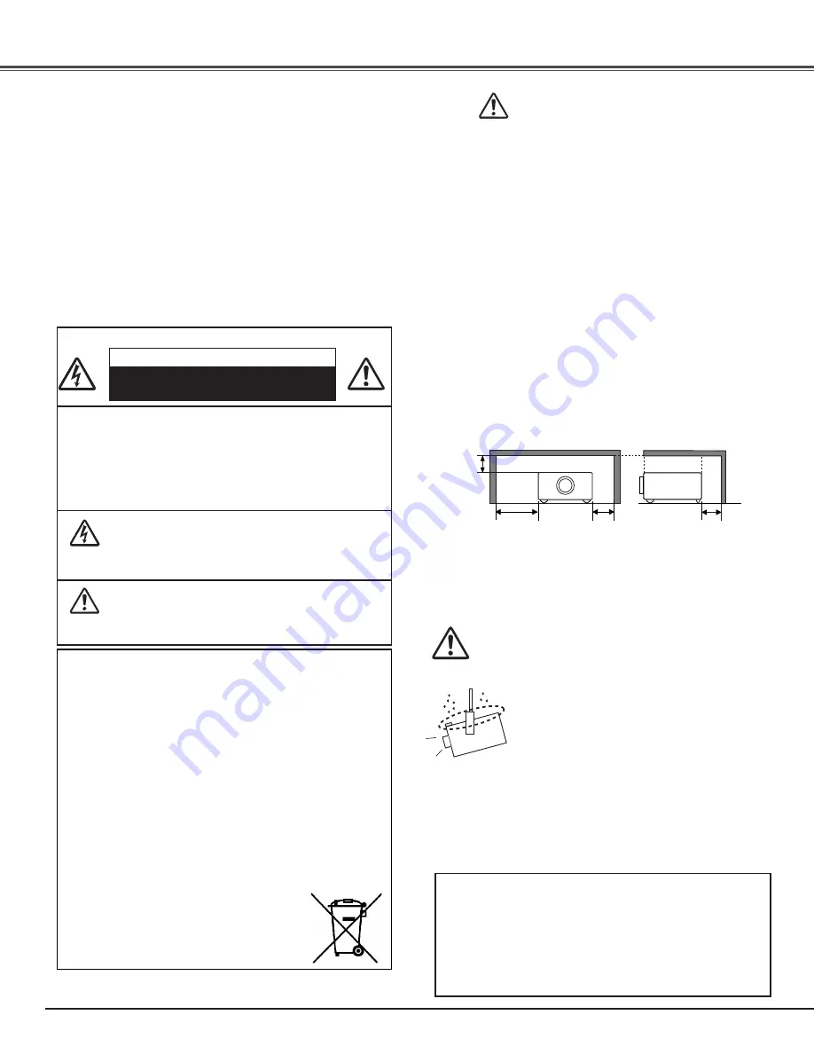
– Install the projector in a proper position. Otherwise it may 

result in fire hazard.

– Allowing the proper amount of space on the top, sides, 

and rear of the projector cabinet is critical for proper air 
circulation and cooling of the unit. The dimensions shown 
here indicate the minimum space required. If the projector 
is to be built into a compartment or similarly enclosed, these 
minimum distances must be maintained. 

– Do not cover the ventilation slot on the projector. Heat build-

up can reduce the service life of your projector, and can also 
be dangerous.

– If the projector is unused for an extended time, unplug the 

projector from the power outlet.

– Do not project the same image for a long time. The 

afterimage may remain on the LCD panels by the 
characteristic of panel.

1.5' (50 cm)

  3' (1 m)

1.5' (50 cm)

1.5' (50 cm)

SIDE and TOP

REAR


CAUTION ON HANGING FROM THE CEILING

When hanging the projector from the 
ceiling, clean the air intake vents, air filters, 
and the top of the projector periodically 
with a vacuum cleaner. If you leave the 
projector unclean for a long time, the 
cooling fans can be clogged with dust, and 
it may cause a breakdown or a disaster.

DO NOT SET THE PROjECTOR IN GREASy, WET, 
OR SMOKy CONDITIONS SUCH AS IN A KITCHEN 
TO PREVENT A BREAKDOWN OR DISASTER . IF THE 
PROjECTOR COMES IN CONTACT WITH OIL OR 
CHEMICALS, IT MAy BECOME DETERIORATED .

To the Owner

CAUTION:TO REDUCE THE RISK OF ELECTRIC 

SHOCK, DO NOT REMOVE COVER 

(OR BACK) . NO USER-SERVICEABLE 

PARTS INSIDE EXCEPT LAMP 

REPLACEMENT .  REFER SERVICING TO 

QUALIFIED SERVICE PERSONNEL .

THIS SyMBOL INDICATES THAT 

DANGEROUS VOLTAGE CONSTITUTING 

A RISK OF ELECTRIC SHOCK IS PRESENT 

WITHIN THIS UNIT .

THIS SyMBOL INDICATES THAT THERE 

ARE IMPORTANT OPERATING AND 

MAINTENANCE INSTRUCTIONS IN THE 

OWNER'S MANUAL WITH THIS UNIT .

CAUTION

RISK OF ELECTRIC SHOCK

DO NOT OPEN

Before installing and operating the projector, read this manual 
thoroughly.
The projector provides many convenient features and 
functions. Operating the projector properly enables you to 
manage those features and maintains it in good condition for 
many years to come.
Improper operation may result in not only shortening the 
product life, but also malfunctions, fire hazard, or other 
accidents.
If your projector seems to operate improperly, read this 
manual again, check operations and cable connections and try 
the solutions in the “Troubleshooting” section in the back of 
this manual. If the problem still persists, contact the dealer 
where you purchased the projector or the service center.

The symbol mark and recycling systems described below 

apply to EU countries and do not apply to countries in other 

areas of the world.

Your product is designed and manufactured with high quality 

materials and components which can be recycled and/or 

reused.

The symbol mark means that electrical and electronic 

equipment, batteries and accumulators, at their end-of-

life, should be disposed of separately from your household 

waste.
Note: 

If a chemical symbol is printed beneath the symbol mark, 

this chemical symbol means that the battery or accumulator 

contains a heavy metal at a certain concentration. This will be 

indicated as follows: Hg: mercury, Cd: cadmium, Pb: lead

In the European Union there are separate collection systems 

for used electrical and electronic equipment, 

batteries and accumulators.

Please, dispose of them correctly at your local 

community waste collection/recycling centre.
Please, help us to conserve the environment 

we live in! 

READ  AND  KEEP THIS  OWNER’S  MANUAL  FOR 
LATER USE .

CAUTION

Not for use in a computer room as defined in the Standard 
for the Protection of Electronic Computer/Data Processing 
Equipment, ANSI/NFPA 75.
Ne peut être utilisé dans une salle d’ordinateurs telle que 
définie dans la norme ANSI/NFPA 75 Standard for Protection 
of Electronic Computer/Data Processing Equipment. 

Summary of Contents for PLV Z3000 - LCD Projector - HD 1080p

Page 1: ...Multimedia Projector MODEL PLV Z3000 Owner s Manual ...

Page 2: ...n full screen Interlace Progressive Conversion High quality picture technology is available that converts an interlaced signal into a progressively scanned one see page 29 Automatic Slide Shutter The automatic slide shutter protects the lens from dust and scratches It opens and closes automatically as you press the POWER ON STAND BY button Wide Selection of Image Modes You can select an ideal imag...

Page 3: ...ecting the AC Power Cord 17 Basic Operation 18 Turning On the Projector 18 Turning Off the Projector 19 How to Operate the On Screen Menu 20 Menu and its Functions 21 Zoom and Focus Adjustment 22 Remote Control Operation 22 Input 24 Input Source and System Selection 24 Image 27 Image Mode Selection 27 Image Adjustment 28 Image Mode Adjustment 28 Picture Adjustment 34 Picture Position and Screen Ad...

Page 4: ...HOCK IS PRESENT WITHINTHIS UNIT THIS SYMBOL INDICATESTHATTHERE ARE IMPORTANT OPERATING AND MAINTENANCE INSTRUCTIONS INTHE OWNER S MANUAL WITHTHIS UNIT CAUTION RISK OF ELECTRIC SHOCK DO NOT OPEN Before installing and operating the projector read this manual thoroughly The projector provides many convenient features and functions Operating the projector properly enables you to manage those features ...

Page 5: ... out parts that could result in a fire or electric shock Never spill liquid of any kind on the projector Do not install the projector near the ventilation duct of air conditioning equipment This projector should be operated only from the type of power source indicated on the marking label If you are not sure of the type of power supplied consult your authorized dealer or local power company Do not...

Page 6: ... TRANSPORTINGTHE PROJECTOR Do not drop or bump the projector otherwise damages or malfunctions may result When carrying the projector use a suitable carrying case Do not transport the projector by courier or any other transport service in an unsuitable transport case This may cause damage to the projector For information about transporting the projector by courier or any other transport service co...

Page 7: ...he Underwriters Laboratories UL and certified by the Canadian Standard Association CSA AC Power Cord has a grounding type AC line plug This is a safety feature to be sure that the plug will fit into the power outlet Do not try to defeat this safety feature Should you be unable to insert the plug into the outlet contact your electrician GROUND THE SOCKET OUTLET SHOULD BE INSTALLED NEARTHE EQUIPMENT...

Page 8: ...ojector Kensington is a registered trademark of ACCO Brands Corporation q Exhaust Vent Front q e r y t u o w Top Controls and Indicators e Automatic Slide Shutter r Projection Lens t Focus Ring y Zoom Lever u Infrared Remote Receiver i Vertical Lens Shift Ring Up Down o Horizontal Lens Shift Ring Left Right 0 Lens Shift Lock 7 i 0 Air flow CAUTION Hot air is exhausted from the exhaust vent Do not ...

Page 9: ... 15 w S VIDEO Connect the S Video output signal from video equipment to this jack p 15 r SERVICE PORT This jack is used to service the projector r y t HDMI 1 HDMI 2 Connect the HDMI output signal from video equipment to these terminals p 16 Note on the HDMI connector Use the HDMI connector less than the size shown below Otherwise you cannot connect use HDMI 1 and HDMI 2 terminals at the same time ...

Page 10: ...ng range pp 44 53 u OK button Execute the item selected or use it to access the submenu items p 20 y POINT ed7 8 buttons Select an item or adjust the setting values in the On Screen Menu r MENU button Open or close the On Screen Menu p 20 q POWER indicator Lights red while the projector is in stand by mode Lights green during operations Blinks red during the cooling off period Blinks green in the ...

Page 11: ...ted image pp 23 28 7 IMAGE ADJ button Display the Image adj Menu items one at a time and directly adjust the selected items pp 23 28 0 OK button Execute the selected item or access the sub menu items p 20 8 0 FREEZE button Freeze the projected image p 23 9 INFO button Display the input source information p 43 1 To ensure safe operation observe the following precautions Do not bend drop or expose t...

Page 12: ...structions Point the remote control toward the projector Infrared Remote Receiver when pressing any buttons Maximum operating range for the remote control is about 16 4 5 m and 60 degrees in front of the projector 16 4 5 m 30 Remote Control Operating Range Open the battery compartment lid Install new batteries into the compartment Replace the compartment lid 1 2 3 When the batteries of the remote ...

Page 13: ... actual sizes This projector is designed to project on a flat projection surface having a focus range of 3 9 1 2 m to 30 2 9 2 m at maximum zoom and 7 9 2 4 m to 60 4 18 4 m at minimum zoom Refer to the figure and table below for the screen size and distance between the projector and screen 40 100 150 300 75 50 150 80 40 30 2 9 2 m 15 1 4 6 m 9 8 3 0 m 7 9 2 4 m Inch Diagonal Center Max Zoom Min Z...

Page 14: ...s Shift Ring Up Down V V W 1 2W downmost leftmost rightmost Vertical Lens Shift Up Down Horizontal Lens Shift Left Right Moving the Lens Note The best image is generally obtained at the central axis of the lens shift With maximum lens shift in each direction image distortion may be observed at the edge of the screen With the maximum horizontal lens shift the maximum vertical lens shift cannot be o...

Page 15: ...Pr Cr COMPONENT Component Use a component cable optional Connecting to Video Equipment Component Component Cable RCA x 3 Note To order the optional cables see page 58 When connecting HDTV equipment to the projector s COMPONENT 1 2 terminals horizontal line noise may be noted only occasionally Then adjust the value of Fine sync The setting can be adjusted from 0 to 31 see page 34 This projector can...

Page 16: ... HDMI output Connecting to Video Equipment HDMI RGB Scart HDMI Video Output Unplug the power cords of both the projector and external equipment from the AC outlet before connecting the cables Note To order the optional cables see page 58 COMPUTER Computer Monitor Out Computer Analog Use a VGA cable commercially available or a DVI VGA cable commercially available DVI VGA Cable VGA Cable Installatio...

Page 17: ...upplied to the projector Installation NOTE ONTHE POWER CORD AC power cord must meet the requirements of the country where you use the projector Confirm the AC plug type with the chart below and proper AC power cord must be used If the supplied AC power cord does not match your AC outlet contact your sales dealer Projector side AC Outlet side To POWER CORD CONNECTOR on your projector Ground To the ...

Page 18: ...not open properly the projector will not be turned on and the POWER indicator will blink orange Press the POWER ON STAND BY button again to restart When Countdown off or Off is selected in the Display function the countdown will not be displayed on the screen p 40 During the countdown period all operations are invalid Image may look dark for a while after turning on the projector Lamp needs some t...

Page 19: ...rned on again the POWER indicator stops blinking Then you can turn the Main On Off switch off and unplug the AC power cord Power off disappears after 4 seconds Turning Off the Projector Note If the automatic slide shutter is closed during operation the projector is automatically turned off for safety Be sure to turn off the projector by pressing the POWER ON STAND BY button on the top control or o...

Page 20: ...tor can be adjusted or set via the On Screen Menu The menus have a hierarchical structure with a main menu that is divided into submenus which are further divided into other submenus For each adjustment and setting procedure refer to respective sections in this manual Top Control Point Right or OK buttons OK button POINT buttons arrowhead Remote Control MENU button How to Operate the On Screen Men...

Page 21: ...urce from among Video S video Component 1 Component 2 HDMI 1 HDMI 2 and Computer For Video and S video inputs choose a video system from AUTO PAL SECAM NTSC NTSC4 43 PAL M and PAL N pp 24 26 y Setting Change various settings Language Advanced menu Menu position Ceiling Rear HDMI 1 setup HDMI 2 setup Highland Background Rename Display Logo Power off confirmation Capture Power management Remote cont...

Page 22: ...ontrol Note See the next page for the description of other buttons Zoom and Focus Adjustment Basic Operation RESET button RESET button Press the RESET button to reset the adjusted data All adjustments return to their previous figures When a main menu item is selected its entire submenu items are reset when a submenu item is selected only the selected item is reset This function is limited to when ...

Page 23: ...ton Basic Operation IMAGE MODE buttons LOGO button SHARPNESS button NO SHOW button FREEZE button Press the COLOR TEMP button to display the Color temp adjustment bar and use the Point 7 8 buttons to select the desired options Press the MENU button after adjusting For details see page 28 COLORTEMP button SHARPNESS button Press the SHARPNESS button to display the Sharpness adjustment bar and use the...

Page 24: ...en the video signal is connected to the COMPONENT 1 jack press C1 C1 When the video signal is connected to the HDMI 1 terminal press H1 H1 INPUT button Video S video PC When the computer signal is connected to the COMPUTER connector press PC Component 1 Component 2 HDMI 1 HDMI 2 Note Before selecting an input source with these buttons each input must be set on a proper signal form via menu operati...

Page 25: ...EO jacks select Video or S video respectively Menu Operation Input Menu When the video signal is connected to the Y Pb Cb Pr Cr jacks select Component 1 or Component 2 The projector automatically detects the incoming video signal and adjusts itself to optimize its performance 3 When Video or S video is selected press the Point 8 button to display the System Menu 4 Use the Point ed buttons to selec...

Page 26: ...nector select RGB Analog RGB Scart When the input terminal is Scart with a DVD player connected to the COMPUTER connector select RGB Scart Source Select Menu Computer Input Computer Press the Point 8 button to display the Source Select Menu Use the Point ed buttons to select the desired source and press the Point 8 or OK buttons The projector automatically tunes to various types of computers based...

Page 27: ...contrasty 3D images in a dark room Creative cinema For viewing images with quiet tones of color and less gradation in a dark room Pure cinema For displaying user preset image mode in the Image adj Menu pp 28 33 User image 1 7 For viewing images faithfully reproduced without any control by the projector in a dark room Natural For viewing video sources such as sports or dramas from TV with clear and...

Page 28: ...nt ed buttons to select the desired item and the Point 7 8 buttons to adjust the setting Press the MENU button after adjusting If you press the OK button after adjusting each item it will enter the main menu Menu Operation Remote Control 3 Use the Point 7 8 buttons to adjust the setting values and press the OK button Image mode can be adjusted for each input source and the adjustment is kept until...

Page 29: ...n Press the Point 7 button to lighten red tone press the Point 8 button to deepen red tone from 31 to 31 White balance Red Press the Point 7 button to lighten green tone press the Point 8 button to deepen green tone from 31 to 31 White balance Green Press the Point 7 button to lighten blue tone press the Point 8 button to deepen blue tone from 31 to 31 White balance Blue Note If any one of the Whi...

Page 30: ... sharpness of image outlines in 4 steps Off Low Mid High Color management Adjust the level phase and gamma of any color You can store up to eight 8 color management data For details see COLOR MANAGEMENT on page 32 Smooth motion Select one of the following options to get smoother images Off Basic correction Low Small correction Mid Medium correction High Large correction 5 5 pull down Select the 5 ...

Page 31: ...in the center of the gamma bar Once you make an adjustment the gamma pointer remains where the adjustment is made The values are set to 0 when no adjustment is made Use the Point 7 8 buttons to move the colored gamma pointer between the gamma bars 9 bars to select a desired gamma bar Use the Point ed buttons to move the colored gamma pointer within the gamma bar from 15 to 15 except for the left a...

Page 32: ...ess the OK button COLOR M Go to COLOR SELECTION EXIT Exit the Color management mode and return to the Advanced menu To store the adjusted data see Store on the next page Press the MENU button when you want to return to the Advanced menu COLOR SELECTION Press the OK button when COLOR M in the Color management list is selected The Color management list disappears and the Color management pointer app...

Page 33: ...and then press the OK button All adjustments return to their previous figures You can also reset the adjusted data by pressing the RESET button on the remote control Reset Press the Point 8 or OK buttons to store the adjusted data The User Image Mode Menu appears Note If you change the image mode see page 27 or turn off the POWER without storing adjusted settings all the adjusted settings will be ...

Page 34: ...n the input signal is from computers select Auto adj and press the Point 8 or OK buttons so that it automatically adjust Fine sync Total dots and Horizontal and Vertical positions to conform to your computer Note Overscan can be selected with the video input only When the digital signal is selected and the image noise appears on the edge of the screen use the Overscan to make adjustment The adjust...

Page 35: ...ange with the vertical adj function See Vertical adj on the next page for details Screen Normal Fit the image to the center of the screen at the normal video aspect ratio of 4 3 Modify the image to fit the screen size by stretching the image to make it look natural When the video signal format is 480i 575i 480p or 575p the 4 3 aspect ratio image is modified to fit the screen size 16 9 aspect ratio...

Page 36: ...ue returns to 0 The Vertical adj dialog box cannot be displayed when the On Screen Menu is on Vertical adj Original signal Image Full Zoom Normal Natural wide Anamorphic 4 3 Composite S video 480i 480p 575i 575p 4 3 Squeeze Composite S video 480i 480p 575i 575p 4 3 Cinesco L B Letterbox 4 3 Vista 16 9 L B Letterbox 16 9 720p 1080i 1080p 16 9 720p 1080i 1080p 4 3 display 16 9 720p 1080i 1080p 21 9 ...

Page 37: ... moves to this icon Press the Point 8 or OK buttons again to activate it Language Advanced menu When this function is On the Advanced menu in the Image Mode Adjustment can be selected Press the Point 8 or OK buttons to switch On Off See Advanced menu on pages 30 31 for details The Setting Menu allows you to set up other various functions described below Language Press the Point 8 or OK buttons to ...

Page 38: ...al is detected Press the Point 8 or OK buttons to switch between each option Blue Project a blue background Logo Project an image selected in the Logo setting Black Project a black background HDMI 1 setup Press the Point 8 or OK buttons to select Normal or Enhanced according to the output signal of video equipment Background Note When the Logo setting see page 40 is set to Off with the Logo backgr...

Page 39: ...t No and press the OK button to continue Another confirmation dialog box appears and select Yes to cancel your entry To return to the on screen keyboard to change the custom name press the MENU button The confirmation dialog box appears Select No and press the OK button to continue Another confirmation dialog box appears and select No The on screen keyboard with a newly entered custom name in the ...

Page 40: ...arting to capture a new image the previously stored image is cleared even if you cancel the capturing Select Yes to stop capturing Select Yes to capture the projected image Logo This function decides on the starting up display from among the following options Press the Point 8 or OK buttons to switch between each option User Show the Image you captured Default Show the factory set logo Off Show th...

Page 41: ...es of the remote control are replaced the remote control code automatically returns to the initial code Code 1 Shutter demo Remote control For reducing power consumption as well as maintaining the lamp life the Power management function turns off the projection lamp when the projector is not used for a certain period When this function is On and if the input signal is interrupted and no button is ...

Page 42: ...operations Factory default This function restores all setting values except for the user s logo the filter counter and the lamp time to the factory default settings Select Yes and press the OK button then another confirmation box appears Factory default Select Factory default and press the Point 8 or OK buttons Return to Factory default appears Select Yes again to restore to the factory default se...

Page 43: ...t source is out of recognition Unknown is displayed The horizontal frequency of the input signal is displayed in KHz or when no signal The vertical frequency of the input signal is displayed in Hz or when no signal Numbers of Hz doubles when during Interlace The cumulative lamp operating time is displayed Direct Operation Press the INFO button on the top control or on the remote control to display...

Page 44: ...check the items below Did you provide appropriate space for the projector to be ventilated Check the installing condition to see if ventilation slots are not blocked Has the projector been installed near an Air Conditioning Heating Duct or Vent Move the installation of the projector away from the duct or vent Is the air filter clean Clean the air filter periodically or replace it with a new one TO...

Page 45: ...age your eyes Do not look into the Air intake vent and Exhaust vent too Use the blower and nozzle only to clean the projector Do not attempt to use them for other purposes Do not use the blower and nozzle against persons particularly to eyes mouth or ears Be especially careful to ensure that children do not put the blower and nozzle into their mouth and swallow them Do not attempt to pull the nozz...

Page 46: ... into the hole Do not attempt to push the nozzle further in or it could break and be stuck inside of the projector Do not open the hole cover except when you clean the inside of the projector to prevent foreign matters from getting into the projector If it is open especially while operating the projector the optical parts could damage Which hole to put the nozzle in When you look at the screen Whe...

Page 47: ...ilter covers Tab Tab Filter cover Air filter When putting back the air filter make sure that the arrows on the filter are facing towards the projector Groove Arrows Push here when you are putting back the air filter Press the latch and release it Take off the filter cover 2 Remove dust and dirt with a soft brush or a vacuum cleaner Be careful not to damage the air filter and do not clean it with w...

Page 48: ...e cleaning Gently wipe the projection lens with a cleaning cloth that contains a small amount of non abrasive camera lens cleaner or use a lens cleaning paper or a commercially available air blower to clean the lens Avoid using an excessive amount of cleaner Abrasive cleaners solvents or other harsh chemicals might scratch the surface of the lens When the projector is not in use make sure that the...

Page 49: ... The glass can shatter and may cause injury Allow the projector to cool for at least 45 minutes before you open the lamp cover The inside of the projector can become very hot Top Control CAUTION Screw Turn off the projector and unplug the AC power cord Let the projector cool for at least 45 minutes Loosen the two 2 screws that secure the lamp Pull out the lamp by using the built in handle 1 3 Repl...

Page 50: ... risk of lamp explosion A Lamp may explode as a result of vibration shock or degradation as a result of hours of use as its lifetime draws to an end Risk of explosion may differ according to the environment or conditions in which the projector and lamp are being used IF A LAMP EXPLODES THE FOLLOWING SAFETY PRECAUTIONS SHOULD BETAKEN If a lamp explodes disconnect the projector s AC plug from the AC...

Page 51: ... distortion and partial imperfect focus see page 14 No image Check the connection between your computer or video equipment and the projector see pages 15 16 See if the input signal is correctly output from your computer For some laptop computers the setting for the monitor output needs to be changed when connecting to a projector See your computer s instruction manual for the setting It takes abou...

Page 52: ...op Bottom reversed Check the Ceiling Rear item see page 37 Check the Ceiling item see page 37 The edge of the image is distorted With maximum lens shift image distortion may be observed see page 14 Auto adj does not work The Auto adj function cannot be operated with the video input some incompatible computer input and digital signals see page 34 Image is distorted or runs off Check Picture adj men...

Page 53: ... is operating normally The projector is in the Power management mode The temperature inside the projector is abnormally high The projector cannot be turned on When the projector is cooled down enough and the temperature returns to normal the POWER indicator emits red light and the projector can be turned on The WARNING indicator keeps blinking Check and clean the air filter The projector has been ...

Page 54: ...ser image 7 Red Green Blue 31 to 31 31 to 31 31 to 31 Sharpness 7 to 7 Lamp Control Normal Auto 1 Auto 2 Eco Gamma 7 to 7 Progressive Off Video Auto Noise reduction On Off Iris mode Iris range Advanced menu Mode 1 Mode 2 Fixed 63 to 0 Transient improvement Color management Contrast enhancement Auto black stretch Off Low Mid High Off Low Mid High Off Low Mid High 5 5 pull down Off Auto Smooth motio...

Page 55: ... When 480i 575i input 8 to 8 When 480i 575i input 15 to 15 Image Screen Lamp status Appendix Lamp time Filter time On Off Normal HDMI 1 setup Enhanced Normal HDMI 2 setup Enhanced D VGA D WXGA Zoom Normal Anamorphic Natural wide Resolution for PC input Unknown D 480i D 480p D 575i D 575p D 720p D 1080i D 1080p Rename Input User image User On Off On Off Code 1 Logo Power off confirmation Power mana...

Page 56: ... 1080i 33 75 30 00 Interlace 1080i 28 12 25 00 Interlace 1080p 56 25 50 00 1080p 67 50 60 00 System mode RESOLUTION H Freq kHz V Freq Hz D VGA 640x480 59 94 60 D WXGA 1280x768 47 776 59 870 D WXGA 1280x768 60 289 74 893 D WXGA 1280x768 68 633 84 837 D 480i 720x480 59 94 60 D 575i 720x575 50 00 D 480p 720x480 59 94 60 D 575p 720x575 50 00 System mode RESOLUTION H Freq kHz V Freq Hz D 720p 1280x720 ...

Page 57: ...acks mini D sub 15 pin x 1 Computer InputTerminal HDMI terminal 19 pin x 2 HDMI InputTerminals 0 to 6 5 Feet Adjustment Power Source AA or LR6 1 5 V ALKALINE Type x 2 Operating Range 16 4 5 m 30 Dimensions 2 13 x 1 04 x 6 81 54 mm x 26 3 mm x 173mm Net Weight 3 4 oz 95 5 g not including batteries Remote Control 480i 480p 575i 575p 720p 1080i and 1080p High DefinitionTV Signal AC 100 120 V 2 9 A Ma...

Page 58: ...2 11 14 15 1 3 5 7 9 11 13 15 17 19 18 16 14 12 10 8 6 4 2 TMDS Data 2 Input Ground TMDS Data 1 Ground TMDS Data 2 TMDS Data 1 Input TMDS Data 2 Input TMDS Data 1 Input TMDS Data 0 Input Ground TMDS Data 0 1 5 2 4 3 6 7 8 Ground TMDS Clock SCL TMDS Clock Input SDA Ground DDC CEC 11 15 12 14 13 16 17 19 PinType A TMDS Data 0 Input TMDS Clock Input 9 10 Plug insert detection 19 18 5V Power Pin Confi...

Page 59: ...59 Dimensions 13 62 346 5 82 147 9 3 45 87 7 6 31 160 3 0 77 19 6 4 62 117 3 3 17 80 5 15 75 400 2 09 53 6 5º 6 06 154 Unit inch mm Appendix ...

Page 60: ...ME4A SANYO Electric Co Ltd ...

Reviews: