-79-
Electrical Adjustments
●
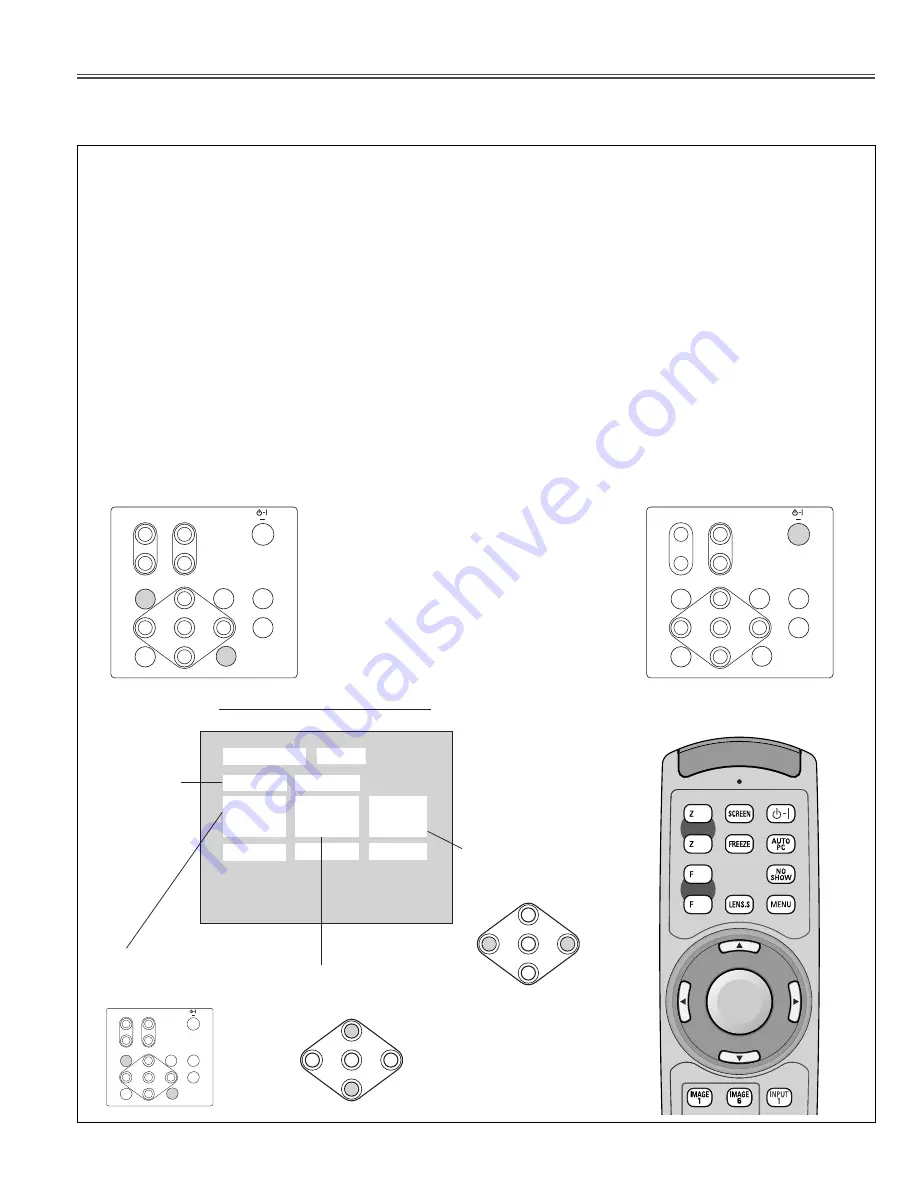
Service Adjustment Menu Operation
Service Mode
0
20
80
Group
Input
Ver.
Data
NO.
SERVICE ADJUSTMENT MENU
Signal Input
Source
Group No.
Select with MENU and
IMAGE buttons.
Item No.
Select with point UP and
DOWN buttons.
Data
Adjust with point LEFT
and RIGHT buttons.
To enter "service mode"
Press "MENU" and "IMAGE" but-
tons on the projector simultaneously
and hold for 3 seconds.
To adjust "service mode"
Adjust service data using the following
control buttons on the projector or the
remote control unit.
"MENU" . . . . . . . . Group No. increases.
"IMAGE" . . . . . . . . Group No. decreases.
"point UP" . . . . . . Item No. increases.
"point DOWN" . . . Item No. decreases.
"point RIGHT" . . . Data value increases.
"point LEFT" . . . . . Data value decreases.
To exit "service mode"
Press "POWER ON-OFF" button
once on the projector or the remote
control unit to quit the service mode.
ZOOM
ON
OFF
FOCUS
MENU
LENS SHIFT
INPUT 1/2
INPUT 3/4
SELECT
AUTO PC ADJ.
IMAGE
<
<
<
<
<
<
<
<
ZOOM
ON
OFF
FOCUS
MENU
LENS SHIFT
INPUT 1/2
INPUT 3/4
SELECT
AUTO PC ADJ.
IMAGE
<
<
<
<
<
<
<
<
Follow the procedures described below for the adjustments with service mode.
1. Turn the projector Power ON.
2. Enter Service adjustment menu.
Press and hold the MENU and IMAGE button on the projector simultaneously for more than 3 seconds, or press
and hold the MENU button on the remote control unit for more than 20 seconds. The service adjustment menu
appears on the screen.
3. Select Adjustment Group No. and Item No. which are to be adjusted.
Select Adjustment Group No. by pressing "MENU" and "IMAGE" buttons.
Press point UP (
e
) and DOWN (
d
) buttons to select Item No.
4. Adjust data value or change setting matter with point LEFT (
7
) and RIGHT (
8
) buttons.
5. Press POWER "ON-OFF" button once and close the service adjustment menu.
SELECT
<
<
<
<
SELECT
<
<
<
<
ZOOM
ON
OFF
FOCUS
MENU
LENS SHIFT
INPUT 1/2
INPUT 3/4
SELECT
AUTO PC ADJ.
IMAGE
<
<
<
<
<
<
<
<
RESET
▲
▲
▲
▲
FOCUS
ZOOM
ON-OFF
SELECT
Remote Control
Summary of Contents for PLV-HD2000E
Page 109: ... 109 IC Block Diagrams ICS1523M Clock Driver IC8209 CXA2151Q RGB Matrix IC271 ...
Page 166: ... 166 MEMO ...
Page 167: ... 167 MEMO ...
Page 168: ... PLV HD2000N E JUL 2006 BB 350 Printed in Japan SANYO Electric Co Ltd ...
Page 194: ...A26 PCB_MA4A BGA side A FANNET_3 K16W MAIN K8L MAIN K401 MAIN K8K MAIN K2203 BGA side B ...
Page 196: ...A28 PCB_MA4A ...
Page 198: ...Diagrams Drawings MA4 HD2000N00 PA4 HD2000E00 ...


