-9-
Lamp Replacement
Lamp replacement
WArNING:
- For continued safety, replace with a lamp assembly of the same
type.
- Allow the projector to cool for at least 45 minutes before you open the
lamp cover. The inside of the projector can become very hot.
- Do not drop the lamp module or touch the glass bulb! The glass can
shatter and cause injury.
WArNING : turN oFF tHe uV lAMP BeFore oPeNING tHe lAMP coVer.
uSe uV rAdIAtIoN eYe ANd SKIN ProtectIoN durING SerVIcING.
Note
- The projector cannot be turned-on with lamp cover removed, because
when the lamp cover is removed, the lamp cover switch is also re-
leased to switch off the lamp circuit.
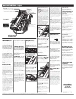
Unplug the AC power cord. Let the projector cool for at least 45
minutes.
Loosen the three (3) screws that secure the lamp. Lift the lamp
out of the projector by using the handles.
1
3
Replace the lamp with a new one and secure the three (3)
screws. Make sure that the lamp is set properly. Push the
lamp cover and secure the screw.
4
Loosen the screw and open the lamp cover.
2
Connect the AC power cord to the projector and turn on the
projector.
5
Procedure
For continued safety, replace with a lamp of the
same type. Do not drop a lamp or touch a glass bulb!
The glass can shatter and may cause injury.
Allow a projector to cool for at least 45 minutes
before you open the Lamp Cover. The inside of the
projector can become very hot.
cAutIoN
cAutIoN
cAutIoN
When replacing the lamp because it has stopped illuminating, there is a possibility that the lamp may be
broken.
If replacing the lamp of a projector which has been installed on the ceiling, you should always assume that the
lamp is broken, and you should stand to the side of the lamp cover, not underneath it. Remove the lamp cover
gently. Small pieces of glass may fall out when the lamp cover is opened. If pieces of glass get into your eyes
or mouth, seek medical advice immediately.
order rePlAceMeNt lAMP
type No.
PoA-lMP131
Service Parts No.
610 343 2069
Lamp Screw
Handles
Screw
Screw
Screw
Lamp Cover
Summary of Contents for PLC-XU301
Page 63: ... 63 IC Block Diagrams FA5550NG P F Control IC621 XR16L5701IL24 UART IC9885 ...
Page 67: ... 67 IC Block Diagrams MR4010 Power OSC IC631 PIC18F67J60 LAN CONTROL IC8801 ...
Page 68: ... 68 IC Block Diagrams FA7703 DC DC Converter IC7811 Sil9127 HDMI Receiver IC8001 ...
Page 95: ...KD5 XU30100 95 Mechanical Parts List ...
Page 96: ... KD5AC MAY 2009 DC 200 Printed in Japan SANYO Electric Co Ltd ...
Page 108: ...A10 SCH_KD5AC NO DATA ...
Page 112: ...A14 PCB_KD5AC NO DATA ...


