
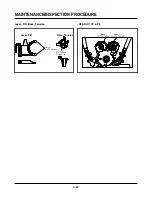

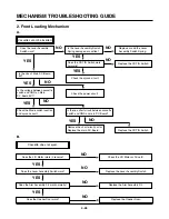
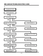

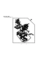
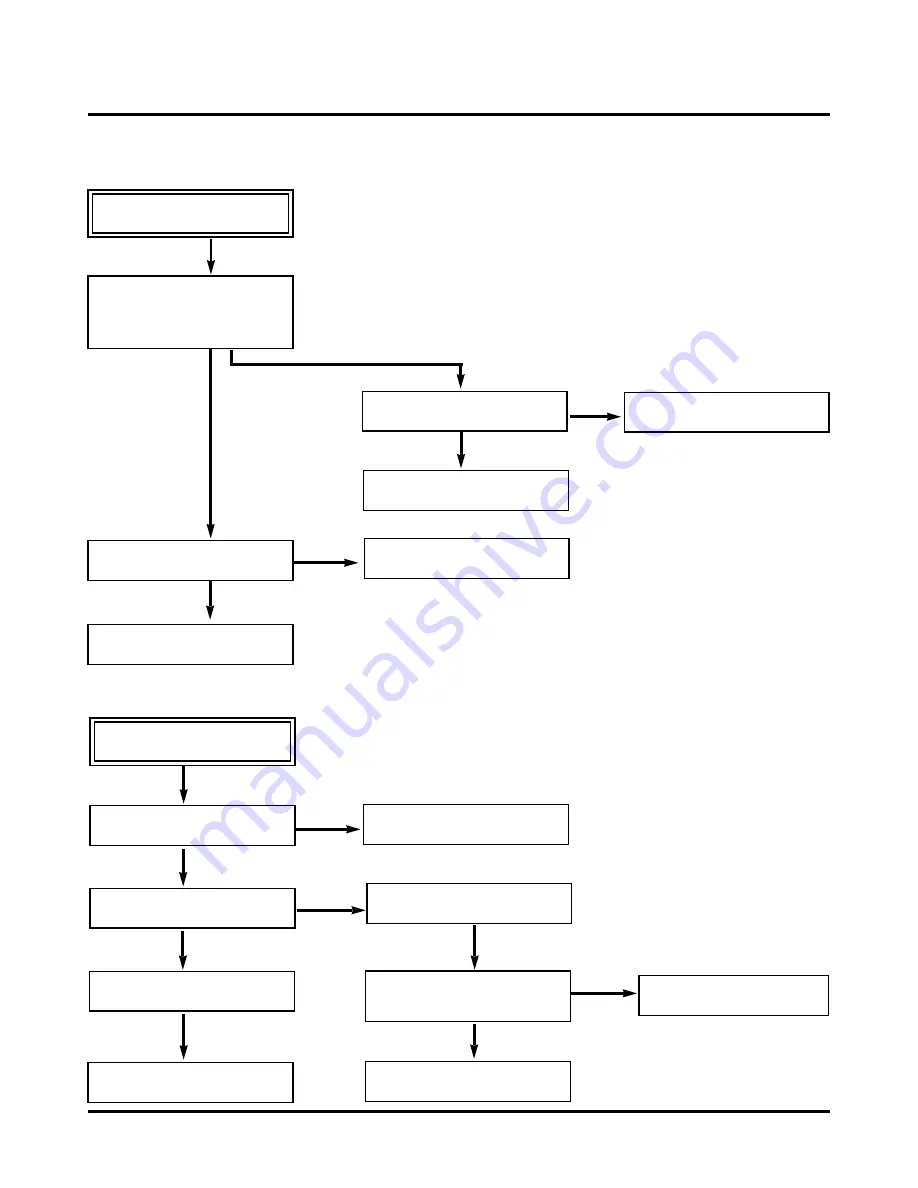
MECHANISM TROUBLESHOOTING GUIDE
4-23
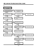
Auto REW doesn't work.
Is the output of END sensor of
supply side "H"?
“H”: more than 3.5V
“L”: less than 0.7V~1V
Is the voltage across IR LED
between 0.8~1.5V?
Replace the IR LED.
Is the Vcc. voltage of End
sensor 5V?
Check the syscon power.
Replace the End sensor.
Check the syscon circuit.
NO
YES
YES
YES
YES
NO
NO
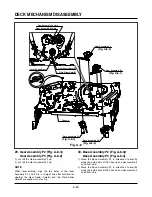
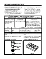
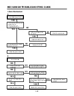
1.Deck Mechanism
A.
NO
NO
NO
No F/R modes.
Is the present mode
F/R Mode?
Is the mode SW assembled
correctly? (refer to page 4-13.)
Is the normal voltage supplied to
the Capstan Motor Vcc1, Vcc2?
Does terminal voltage(Vctl) of
Capstan Motor supply side more
than 4V?
Check the servo, power
circuits.
Replace the Capstan Motor.
Does the Capstan Motor rotate?
Do the T/Up, Supply Reel
rotate?
Check the syscon circuit.
YES
YES
YES
YES
YES
YES
B.
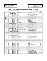
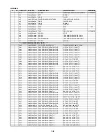
Summary of Contents for HV-DX2E
Page 36: ...3 32 3 33 2 TU IF NICAM A2 CIRCUIT DIAGRAM EE MODE VIDEO TU MODE AUDIO COMBI SCART SANYO ...
Page 41: ...3 42 3 43 7 TIMER CIRCUIT DIAGRAM SRC1203 SRC1203 LD601 C6G1 C6G2 100M 100M ...
Page 45: ...3 50 3 51 PRINTED CIRCUIT DIAGRAMS 1 MAIN P C BOARD LOCATION GUIDE ...
Page 64: ... 02 12 04 R17149A COMBI SCART SANYO DAP202K 3 76 3 77 6 JACK CIRCUIT DIAGRAM ...
Page 69: ...LOCATION GUIDE 3 86 3 87 PRINTED CIRCUIT DIAGRAMS 1 MAIN P C BOARD TOP VIEW ...
Page 70: ...LOCATION GUIDE 3 88 3 89 2 MAIN P C BOARD BOTTOM VIEW ...