

5-2
DECK MECHANISM DISASSEMBLY
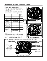
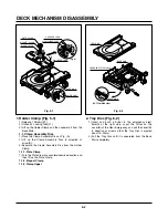
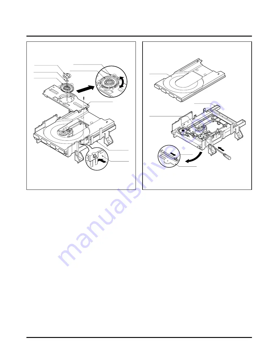
1. Holder Clamp (Fig. 5-1)
1) Release 1 Screws(S1).
2) Unhook 2 Locking Tabs(L1).
3) Lift up the Holder Clamp and then separate it from the
Base Main.
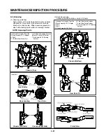
1-1. Clamp Assembly Disc
1) Place the Clamp Assembly Disc as Fig. (A)
2) Lift up the Clamp Assembly Disc in direction of
arrow(A).
3) Separate the Clamp Assembly Disc from the Holder
Clamp.
1-1-1. Plate Clamp
1) Turn the Plate Clamp to counterclockwise direction and
then lift up the Plate Clamp.
1-1-2. Magnet Clamp
1-1-3. Clamp Upper
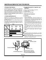
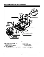
2. Tray Disc (Fig. 5-2)
1) Insert and push a Driver in the emergency eject
hole(A) at the right side, or put the Driver on the
Lever(B) of the Gear Emergency and pull the Lever(B)
in direction of arrow so that the Tray Disc is ejected
about 15~20mm.
2) Pull the Tray Disc until it is separated from the Base
Main completely.
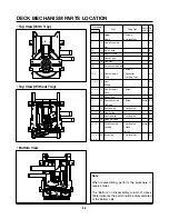
HOLDER CLAMP
CLAMP ASSEMBLY DISC
PLATE CLAMP
MAGNET CLAMP
CLAMP UPPER
(S1)
(L1)
(L1)
HOLDER CLAMP
BASE MAIN
HOLDER CLAMP
(Fig. A)
(A)
TRAY DISC
EMERGENCY EJECT HOLE
LEVER
BASE MAIN
BASE MAIN
BOTTOM SIDE VIEW
(A)
(B)
Fig. 5-1
Fig. 5-2
Summary of Contents for HV-DX2E
Page 36: ...3 32 3 33 2 TU IF NICAM A2 CIRCUIT DIAGRAM EE MODE VIDEO TU MODE AUDIO COMBI SCART SANYO ...
Page 41: ...3 42 3 43 7 TIMER CIRCUIT DIAGRAM SRC1203 SRC1203 LD601 C6G1 C6G2 100M 100M ...
Page 45: ...3 50 3 51 PRINTED CIRCUIT DIAGRAMS 1 MAIN P C BOARD LOCATION GUIDE ...
Page 64: ... 02 12 04 R17149A COMBI SCART SANYO DAP202K 3 76 3 77 6 JACK CIRCUIT DIAGRAM ...
Page 69: ...LOCATION GUIDE 3 86 3 87 PRINTED CIRCUIT DIAGRAMS 1 MAIN P C BOARD TOP VIEW ...
Page 70: ...LOCATION GUIDE 3 88 3 89 2 MAIN P C BOARD BOTTOM VIEW ...