


3-4
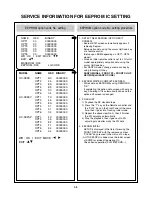
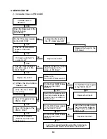
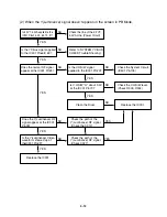
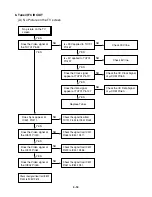
ELECTRICAL TROUBLESHOOTING GUIDE
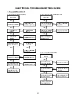
1. Power(SMPS) CIRCUIT
NO 5.3VA.
Replace the F101.
(Use the same Fuse)
Is the F101 normal?
Is the R101
normal?
Is the BD101
normal?
NO
NO
NO
NO
NO
NO
Replace the
BD101.
Replace the R101.
Is the D102
normal?
Check or Replace
the D102.
Replace the D112.
Replace the IC103.
YES
YES
YES
YES
YES
YES
YES
Is Vcc(8.5~21V) sup-
plied to IC101 Pin7?
NO
Is the D112 normal?
Is there about 2.5V
at the IC103 Vref?
Check the Main PCB
5.3VA/5.0V Line short?
(1) No 5.3VA (SYS/Hi-Fi/TUNER)
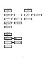
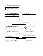
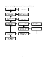
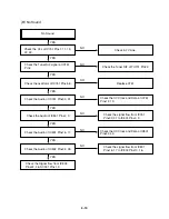
NO 12VA.
Check or Replace
the D110.
Is the Vcc(13V) supplied
to (+) terminal in D115?
Check or Replace
the Motor Vcc.
Is the Vcc(12V) supplied
to (-) terminal in D115?
NO
NO
Replace the D115.
YES
YES
YES
(2) No 12VA (TO CAP, DRUM MOTOR)
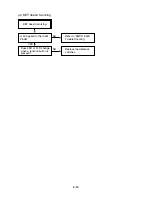
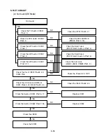
NO 5V.
5.3VA Line Check.
Is 5.3VA put into
the Q160 Emitter?
Is about 5V put into
the Q160 Base?
Is the Q162 Base
“H”?
NO
NO
Check the Power
Control.
NO
Check or Replace the Q162,
R157, R158, R159, D121.
YES
YES
YES
Check or Replace
the Q162/Q160.
YES
(3) No 5V (SYS/Hi-Fi/TUNER)
Summary of Contents for HV-DX2E
Page 36: ...3 32 3 33 2 TU IF NICAM A2 CIRCUIT DIAGRAM EE MODE VIDEO TU MODE AUDIO COMBI SCART SANYO ...
Page 41: ...3 42 3 43 7 TIMER CIRCUIT DIAGRAM SRC1203 SRC1203 LD601 C6G1 C6G2 100M 100M ...
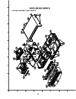
Page 45: ...3 50 3 51 PRINTED CIRCUIT DIAGRAMS 1 MAIN P C BOARD LOCATION GUIDE ...
Page 64: ... 02 12 04 R17149A COMBI SCART SANYO DAP202K 3 76 3 77 6 JACK CIRCUIT DIAGRAM ...
Page 69: ...LOCATION GUIDE 3 86 3 87 PRINTED CIRCUIT DIAGRAMS 1 MAIN P C BOARD TOP VIEW ...
Page 70: ...LOCATION GUIDE 3 88 3 89 2 MAIN P C BOARD BOTTOM VIEW ...