


3-11
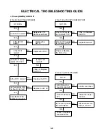
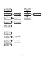
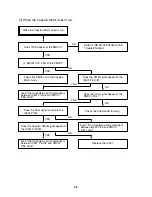
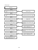
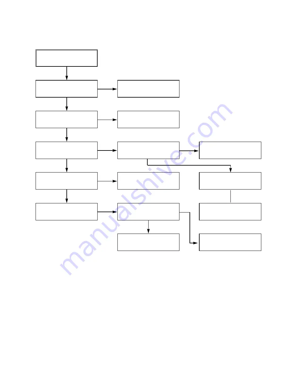
4. Y/C CIRCUIT
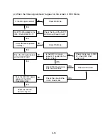
(1) No Video in EE Mode,
No Video in EE Mode
Check the 24Pin of Tuner.
Does the Video signal
appear at the IC301 Pin48?
Is 5V applied to the IC301
Pins18, 24, 42, 55, 72, 91?
Does the Video signal
appear at the IC301 Pin65?
Does the Video signal
appear at the IC501 Pin19?
Does the Video signal
appear at the Emitter termi-
nal of the Q305, Q309?
Check the 5.2VT, 5.3VA
Line. (Power Circuit)
Is I
2
C BUS signal applied to
the IC301 Pins68, 69?
Check C315.
Chck the path of the signal
between the IC301 Pin65
and IC501 Pin17.
Replace the IC301.
Does the REG 12VT, 5.4VA
appear at the Emitter termi-
nal of the Q804, Q308.
Replace the Q804, Q308.
Check the 12VT, 5.4VA
Line. (Power Circuit)
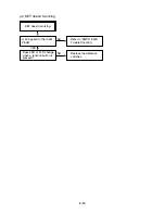
Check the System Circuit.
(Refer to ‘SYSTEM I
2
C BUS
CHECK Trouble Shooting’)
YES
YES
YES
YES
YES
YES
YES
NO
NO
NO
NO
NO
NO
NO
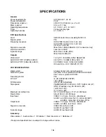
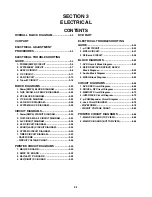
Summary of Contents for HV-DX2E
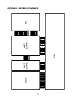
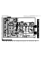
Page 36: ...3 32 3 33 2 TU IF NICAM A2 CIRCUIT DIAGRAM EE MODE VIDEO TU MODE AUDIO COMBI SCART SANYO ...
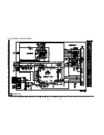
Page 41: ...3 42 3 43 7 TIMER CIRCUIT DIAGRAM SRC1203 SRC1203 LD601 C6G1 C6G2 100M 100M ...
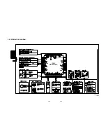
Page 45: ...3 50 3 51 PRINTED CIRCUIT DIAGRAMS 1 MAIN P C BOARD LOCATION GUIDE ...
Page 64: ... 02 12 04 R17149A COMBI SCART SANYO DAP202K 3 76 3 77 6 JACK CIRCUIT DIAGRAM ...
Page 69: ...LOCATION GUIDE 3 86 3 87 PRINTED CIRCUIT DIAGRAMS 1 MAIN P C BOARD TOP VIEW ...
Page 70: ...LOCATION GUIDE 3 88 3 89 2 MAIN P C BOARD BOTTOM VIEW ...