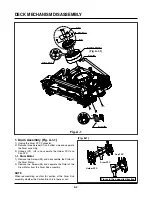

DECK MECHANISM DISASSEMBLY
4-5
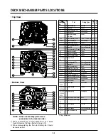
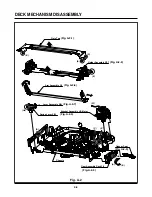
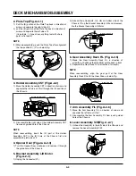
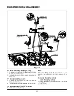
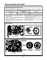
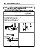
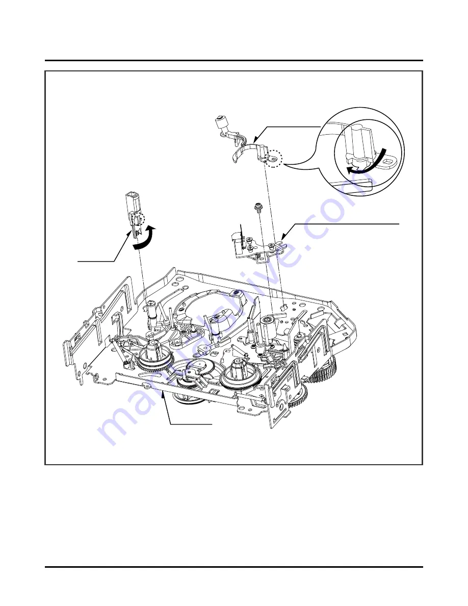
9. Arm Assembly Cleaner (Fig. A-3-1)
1) Breakaway the (A) portion as Fig. A-3-1 from the
embossing of the Chassis, turn the Arm assembly
Cleaner to clockwise direction and lift it up.
10. Head F/E (Fig. A-3-2)
1) Breakaway the (A) portion of the Head F/E from the
embossing of the Chassis, turn it to counterclockwise
direction and lift it up.
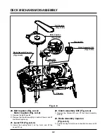
11. Base Assembly A/C Head (Fig. A-3-3)
1) Remove the Screw(S4) and lift the Base Assembly A/C
Head up.
(A)
Arm Assembly
Cleaner
Base Assembly A/C Head
(S4)
Head F/E
(A)
Chassis
Fig. A-3
(Fig. A-3-1)
(Fig. A-3-3)
(Fig. A-3-2)
Summary of Contents for HV-DX2E
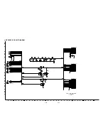
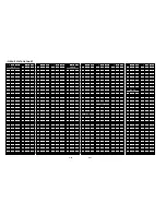
Page 36: ...3 32 3 33 2 TU IF NICAM A2 CIRCUIT DIAGRAM EE MODE VIDEO TU MODE AUDIO COMBI SCART SANYO ...
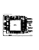
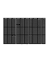
Page 41: ...3 42 3 43 7 TIMER CIRCUIT DIAGRAM SRC1203 SRC1203 LD601 C6G1 C6G2 100M 100M ...
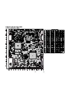
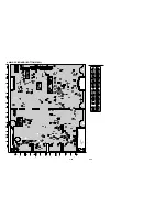
Page 45: ...3 50 3 51 PRINTED CIRCUIT DIAGRAMS 1 MAIN P C BOARD LOCATION GUIDE ...
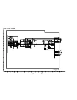
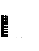
Page 64: ... 02 12 04 R17149A COMBI SCART SANYO DAP202K 3 76 3 77 6 JACK CIRCUIT DIAGRAM ...
Page 69: ...LOCATION GUIDE 3 86 3 87 PRINTED CIRCUIT DIAGRAMS 1 MAIN P C BOARD TOP VIEW ...
Page 70: ...LOCATION GUIDE 3 88 3 89 2 MAIN P C BOARD BOTTOM VIEW ...