background image

NAMES AND FUNCTIONS OF PARTS

3

English

15

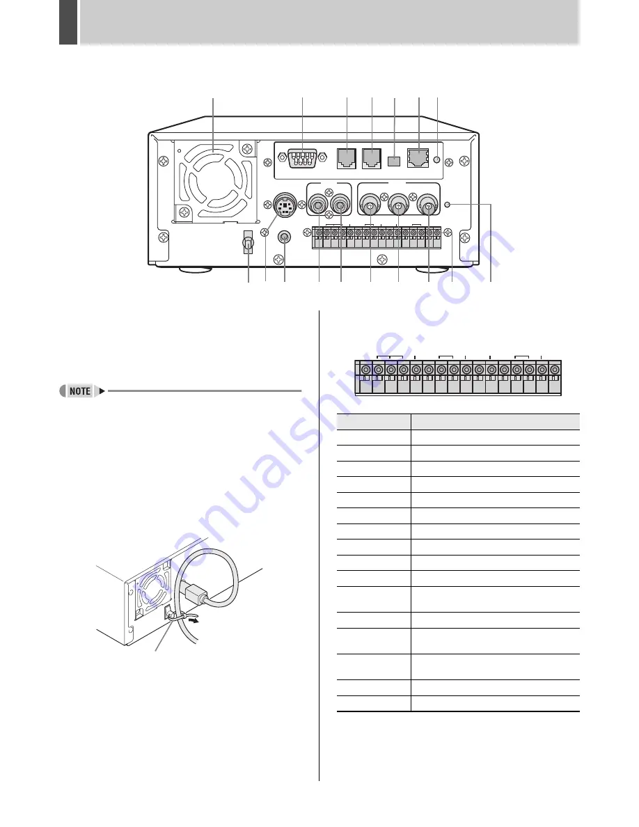
Rear panel

1. Fan

2. RS-232C terminal (when option board is installed)

3. RS-485 terminal A (when option board is installed)

4. RS-485 terminal B (when option board is installed)

z

Do not connect the RS-485 A and RS-485 B connectors 
to a phone line.

5. RS-485 termination switch (when option board is 

installed)

6. LAN terminal (when option board is installed)

7. LAN link indicator (when option board is installed)

8. Power cord holder

Secure the power cord to the holder using the cord tie 
(accessory) as shown in the illustration.

9. AC power socket (AC IN)

10. Wired remote control terminal

11. AUDIO IN terminal

12. AUDIO OUT terminal

13. VIDEO IN terminal

14. VIDEO LOOP OUT terminal

15. VIDEO OUT terminal

16. Control and alarm terminals

17. ALL RESET switch

Resets the recorder’s microcomputer. Menu settings are 
not reset.
Resets the clock and backup mode setting.

ALL

RESET

LAN

OUT

LOOP OUT

VIDEO

NON-REC

COM IN RESET OUT OUT

OUT

OUT OUT

OUT FULL FULL

COM

COM

COM

IN

IN

CLOCK WARNING ALARM

SERIES SW

DC IN

REMOTE

IN

OUT

IN

OFF   ON

RS485

TERMINATE

RS485

RS232C

B

A

AUDIO

ALARM

1

2

6

3

11

13

14

12

15

16

7

10

4

5

9

8

17

Power cord tie

Pin

Signal

COM

Ground

ALARM IN

Alarm input

ALARM RESET IN Alarm reset input

ALARM OUT

Alarm output

NON REC OUT

Non rec out terminal

COM

Ground

CLOCK IN

Clock adjust input

CLOCK OUT

Clock adjust output

WARNING OUT

Warning out terminal

DISK FULL OUT

HDD space warning output

ALARM FULL 
OUT

Alarm-recording area space warning output

COM

Ground

SERIES IN

Input terminal used when recording with 
multiple digital video recorders connected.

SERIES OUT

Output terminal used when recording with 
multiple digital video recorders connected.

SWITCH OUT

Switch output

COM

Ground

NON-REC

COM IN RESET OUT OUT

OUT

OUT OUT

OUT FULL FULL

COM

COM

COM

IN

IN

CLOCK WARNING ALARM

SERIES SW

ALARM

e05_l8had_us_7.fm  Page 15  Friday, March 12, 2004  9:46 AM

Summary of Contents for DSR - 300

Page 1: ......

Page 2: ...g Electrical Shock and Fire z Do not handle the power cord with wet hands z Do not pull on the power cord when disconnecting it from an AC wall outlet Grasp it by the plug z If any liquid is spilled on the unit unplug the power cord immediately and have the unit inspected at a factory authorised service center z Do not place anything directly on top of this unit SERVICE This unit is a precision in...

Page 3: ... date time z Searching for intruder motion using motion detection search The security lock function lets you restrict users for data and equipment management JP 72 Expandable can be connected to a PC z Support for CompactFlash cards allows recorded images to be copied z Images can be recorded to the hard disk and played back from the multiplexer z When the separately sold VZU COM300 interface boar...

Page 4: ...ideo recorder P xx indicates the page to be referred to Copyright z This manual and software are copyrighted by Sanyo Electric Co Ltd z Brand and product names used in this manual are the trademarks or registered trademarks of their respective companies z Except for personal use copyright law prohibits the use of recorded copyrighted images without the permission of the copyright holder ...

Page 5: ... area 20 Built in hard disk 20 Selecting the recording method 20 2 SETTING THE LANGUAGE CLOCK 21 To change the language 21 Setting the time 22 3 NORMAL RECORDING TIMER RECORDING 23 Normal recording 23 Timer recording 23 4 ALARM AND PRE ALARM RECORDING 24 Alarm recording 24 Pre alarm recording 25 5 NORMAL RECORDING TIMER RECORDING PLAYBACK 26 Playback 26 Fast forward playback fast rewind playback 2...

Page 6: ...h the same image quality 60 To cancel all set timer reservations 61 Timer reservations spanning more than 24 hours 62 7 HOLIDAY SET 63 8 ALARM REC MODE SET 64 Setting alarm recording 64 Setting pre alarm recording 66 Setting the alarm trigger 66 Setting the motion sensor 67 1 DISPLAY VIDEO LOSS SET 68 DISPLAY SET and VIDEO LOSS SET setting items 68 Settings 68 2 RS 232C RS 485 SET when optional in...

Page 7: ... 93 Controlling from the unit 95 Messages displayed when connected 95 3 OPERATION PANEL FUNCTIONS AND RESTRICTIONS when optional interface board is installed 96 1 SETTINGS when optional interface board is installed 97 Making menu selection 97 Menu structure 98 2 MENU SPECIFIC SETTINGS when optional interface board is installed 99 1 CLOCK SET 99 2 DAYLIGHT SAVING EXT CLOCK SET 99 3 VIDEO INPUT SET ...

Page 8: ...rface board is installed 118 Basic operation 118 Search menu 118 4 OPERATIONS IN SEARCH MODES when optional interface board is installed 119 1 ALARM SEARCH 119 2 ALARM THUMBNAIL SEARCH 119 3 TIME DATE SEARCH 120 4 ARCHIVE AREA SEARCH 120 5 MOTION DETECTION SEARCH 121 5 SAVING RECORDED IMAGES when optional interface board is installed 122 Copying to the archive area 122 Downloading to a PC 123 Imag...

Page 9: ...ty buildup Handling the HDD unit by itself If transporting or storing the HDD unit by itself always be sure to pack it in the specified packing first In addition use a method of transportation that minimizes the vibration If the HDD becomes damaged handle the unit and the damaged HDD that has been removed in order for it to be replaced carefully to prevent the problem from being aggravated until a...

Page 10: ...e chemicals on the cabinet Do not allow rubber or vinyl products to come into contact with the digital video recorder for extended periods Doing so may break down the finish or strip the paint During extended disuse Extended disuse may cause problems in functions so turn the power on and operate the unit occasionally during such periods Backup battery The digital video recorder comes with a built ...

Page 11: ...reason it is not recognized by the unit remove the power plug from the wall outlet wait for approximately 30 seconds and then remove the HDD 1 Connect the removable HDD s connector and place the HDD inside the tray Remove the brown antistatic sheet inside the tray z Assemble the two sockets in such a way that the red wires are positioned within them 2 Assemble and tighten the 4 screws Screw tighte...

Page 12: ...time with the indicator s flashing The HDD indicator turns off 2 When the CHANGE DISK indicator lights in green and the HDD indicator turns off insert the tray release key and turn it in the direction of the arrow This action will cause the HDD tray lock to be released z An alarm will be sounded if the tray release key is turned when the CHANGE DISK indicator is lit in red or before the HDD indica...

Page 13: ...e handle causes the HDD tray lock to be released 4 Pull the clasp release the lock and remove the cover 5 Remove the 4 screws take the removable HDD out of the tray and release the connector z Whenever the unit is to be transported ensure that the HDD tray is removed from the unit and packaged separately ...

Page 14: ... flashes 10 TIMER button JP 23 When pressed while recording is stopped the unit enters timer record standby When the set time arrives the digital video recorder starts timer recording 11 ALARM button JP 30 When the or button is pressed during playback the unit skips to the next earlier or later alarm 12 SEARCH button JP 29 z When the button is pressed while recording or stopped the search setting ...

Page 15: ... operation display can be moved or hidden 20 TIMER indicator JP 23 The indicator lights when the unit enters timer record standby 21 FULL indicator JP 23 The indicator begins to flash when the remaining available memory in the hard disk s normal recording area reaches the setting value When the recording area becomes full this indicator turns on and recording will be stopped 22 ALARM FULL indicato...

Page 16: ...Menu settings are not reset Resets the clock and backup mode setting ALL RESET LAN OUT LOOP OUT VIDEO NON REC COM IN RESET OUT OUT OUT OUT OUT OUT FULL FULL COM COM COM IN IN CLOCK WARNING ALARM SERIES SW DC IN REMOTE IN OUT IN OFF ON RS485 TERMINATE RS485 RS232C B A AUDIO ALARM 1 2 6 3 11 13 14 12 15 16 7 10 4 5 9 8 17 Power cord tie Pin Signal COM Ground ALARM IN Alarm input ALARM RESET IN Alarm...

Page 17: ...e screwdriver to secure the cable in place Basic connections ALL RESET LAN OUT LOOP OUT ALARM NON REC COM IN RESET OUT OUT OUT OUT OUT OUT FULL FULL COM COM COM IN IN CLOCK WARNING ALARM SERIES SW DC IN REMOTE IN OUT IN OFF ON RS485 TERMINATE RS485 RS232C B A AUDIO VIDEO Microphone sold separately Amp sold separately CCTV camera sold separately Video input terminal To audio input terminal Multiple...

Page 18: ...parately ALL RESET LAN OUT LOOP OUT ALARM NON REC COM IN RESET OUT OUT OUT OUT OUT OUT FULL FULL COM COM COM IN IN CLOCK WARNING ALARM SERIES SW DC IN REMOTE IN OUT IN OFF ON RS485 TERMINATE RS485 RS232C B A ALL RESET LAN OUT LOOP OUT ALARM NON REC COM IN RESET OUT OUT OUT OUT OUT OUT FULL FULL COM COM COM IN IN CLOCK WARNING ALARM SERIES SW DC IN REMOTE IN OUT IN OFF ON RS485 TERMINATE RS485 RS23...

Page 19: ...he CHANGE DISK indicator flashes Contact a Sanyo Authorized Service Centre if the CHANGE DISK indicator flashes 4 flashes per second The hard disk is checked automatically at power ON If a hard disk problem is found the CHANGE DISK indicator flashes and the hard disk must be replaced or reformatted If you need to save images stored on the disk contact a Sanyo Authorized Service Centre 1 flash per ...

Page 20: ...you set an alarm using the ALARM REC MODE SET menu item the alarm display area displays the following information z When alarm recording is set ALARM is displayed ALARM is flashed during alarm recording z When pre alarm recording is set PRE is displayed When an alarm occurs PRE disappears ALARM is displayed and the number of alarms is shown The total number is indicated in the alarm display z When...

Page 21: ...0EN 10FPS B Alarm recording area C Archive area A Normal recording area Hard disk s recording area 80 1 19 Recording mode Recording method Normal recording Manual During monitoring recording is performed when the REC STOP button is pressed Timer recording Automatic Recording is carried out in accordance with timer settings Recording mode Recording method Alarm recording Automatic Recording is carr...

Page 22: ...with the cursor positioned on ENGLISH 3 Press the button then the or button to select the desired language The set item flashes 4 When you have made a selection press the button The cursor moves to the date and time The language has now been set To return to the normal screen press the EXIT OSD button button button MENU button button EXIT OSD button Item Setting Description 1 LANGUAGE SET ENGLISH ...

Page 23: ... The cursor is positioned on ENGLISH 3 Press the or button to move the cursor to the date and time under CLOCK SET 4 Press the button 01 indicating the month flashes 5 Press the or button to select 05 6 Press the button 01 indicating the day flashes 7 Use the same procedure to set the day 20 in this example year 2004 hour 08 and minute 30 When you have set the minute the cursor moves to MODE under...

Page 24: ... image in the normal recording area at the set time 1 Press the TIMER button The TIMER indicator lights and the digital video recorder enters timer recording standby mode z A warning tone sounds if timer recording has not been set 1 See P 60 for how to set timer recording 2 When the time specified in the timer settings arrives the REC STOP indicator lights the recording symbol appears in the scree...

Page 25: ...n screen z The panel s ALARM indicator flashes z If an alarm occurs during normal recording or timer recording the recording operation will be ended and it will restart after the end of alarm recording z When the normal recording area is set to 1 alarm recording is possible for the complete memory available in the alarm recording area For 1 and other settings up to 16 000 items are recorded per ha...

Page 26: ...recorded in a repetitive fashion in a section of the alarm recording area as set for pre alarm recording by DURATION Pre alarm recording is automatically ended and alarm recording starts z PRE from the operation display area is replaced by ALARM and the ALARM indicator flashes z When you record for the first time the default settings are used For details regarding changing of the image quality or ...

Page 27: ...t is started 2 Press the PLAY STOP button Playback ends Playing back an image near the point of recording The digital video recorder prioritizes recording operations so the playback image may pause temporarily During playback press the or button When you press the button appears in the operation display and the playback fast forwards When you press the button appears in the operation display and t...

Page 28: ...g reverse playback press the or button The speed changes by one increment decrement each time you press the button z When the images from each recording area are played back in succession the quality of the picture may drop momentarily as playback switches from one recording area to another z If normal fast forward or fast rewind playback is carried out either for playback during alarm recording o...

Page 29: ...he specified channel are played back z The specification of a channel for playback will only be possible when a multiplexer capable of decoding the channel information i e channel number is connected z When this operation is carried out only the specified channel is played back No other channels will be displayed z When a channel is selected the multiplexer title information date information and o...

Page 30: ... search and play back alarm images from the recording list 2 ALARM THUMBNAIL SEARCH JP 31 Lets you search and play back alarm images using thumbnails 3 TIME DATE SEARCH JP 31 Lets you search and play back recorded images by date time 4 ARCHIVE AREA SEARCH JP 33 Lets you search and play back recorded images stored or copied to the archive area 5 MOTION DETECTION SEARCH JP 33 Lets you search and pla...

Page 31: ...screen You can display up to 8 alarm images z To display the next previous image Press the or button z To display the items on the next page Press the ALARM button The next 8 items are displayed chronologically z To end search mode Press the SEARCH button 4 Press the button The selected image is played back on the full screen To display pre alarm images After starting playback of alarm images foun...

Page 32: ...he image of the next previous page is displayed as a thumbnail z To end search mode Press the SEARCH button 5 Press the button The selected image is played back on the entire screen z In the same way as for alarm searching playback is only possible within each alarm recording Play the previous or subsequent alarm image using the ALARM button Follow the procedures below to play back an image record...

Page 33: ...t 26 the day 3 Press the button then the or button to select 04 the year 4 Press the button then the or button to select 20 the hours 5 Press the button to select 00 the minutes then press the button The cursor moves to PREVIEW 5 Press the button Images are searched and a preview is displayed z If no image exists for the specified time The image for the time closest to the specified time is displa...

Page 34: ...r variations from these images as a result of the presence of an intruder or the like can be detected and the corresponding images can be played back z When performing a motion detection search for a multiplexer image set MULTIPLEXER from 2 VIDEO INPUT SET to anything other than NO USE JP 52 z When a multiplexer capable of decoding channel information is connected a camera number or channel can be...

Page 35: ...ch recording area are displayed 2 END The date and time for the final screen stored in each recording area are displayed 3 MOTION SENSOR The motion sensor is displayed 4 PREVIEW The selected start time is displayed 5 VIEW The selected image is played back on the entire screen 8 Set the motion sensor 1 Press the button 2 Press the or button to set the start date and time i e 10 AM on the same day f...

Page 36: ...een If NOT FOUND is displayed No motion sensors have been set A motion sensor must be set to allow a screen to be displayed 1 Press the or button to select VIEW 2 Press the button Normal playback will be started for the specified image Using this unit in combination with a multiplexer z By specifying the camera number or channel and performing MOTION DETECTION SEARCH playback can be carried out fo...

Page 37: ...rom the archive area to a CompactFlash card before this procedure is carried out z Audio will not be copied together with images from the archive area to a CompactFlash card Audio will be copied together when copying images from the normal recording area or alarm recording area z The application DVR Viewer will be needed in order to playback images and audio copied to a CompactFlash card on a PC V...

Page 38: ... maximum possible setting for images seconds and minutes is 60 z Copying of alarm recordings can only be carried out one alarm at a time 8 Press the button The cursor moves to START 9 Press the button Copying to the archive area starts When this has been completed COPY FINISHED is displayed To cancel a copy operation Press the COPY button to cancel the current copy Example Copying a specified 10 m...

Page 39: ... to select PICTURES Settings indicates default setting z Up to 40 000 images can be copied Copying will stop when this number has been reached z Copying of alarm recordings can only be carried out one alarm at a time 7 Press the button Copying an archive area image to a CompactFlash card or Microdrive COPY button 1 Open the cover 2 Insert the CompactFlash card into the CompactFlash card slot in th...

Page 40: ...d in sequence starting with IMG00001 Each sub directory can hold up to 200 individual images 4 To view images on your PC open the file INDEX HTM found in each date folder using a browser i e Internet Explorer 5 0 or later You will then be able to view the JPEG images individually or in slide show format etc z JPEG images JPEG files contain field images and for this reason they will be 50 compresse...

Page 41: ...O CF then press the button The WARNING screen is displayed 2 Press the or button to select YES then press the button 1 The saving process begins 2 When this process has been completed SAVING FINISHED is displayed A file named MENUCOPY TXT is created in the CompactFlash card directory Use the following procedure to load menu settings saved on a CompactFlash card back into the unit z When loading a ...

Page 42: ...n press the button The cursor is positioned on SAVE MENUS TO CF z When loading menu settings COPY RECORDING AREA SETTINGS should normally be set to NO If set to YES hard disk initialization will be carried out as part of the loading process and all recorded data will be lost 3 Press the or button to select LOAD MENUS FROM CF then press the button The WARNING screen is displayed 4 Press the or butt...

Page 43: ... bottom of each main menu screen and the display will switch to the corresponding screen when the button is then pressed 2 Press the or button to select a menu Example 3 RECORDING AREA SET When you move the cursor the selected item is displayed in reverse 3 Press the button The selected sub menu appears The cursor is positioned on the first setting item 4 Press the EXIT OSD button The display retu...

Page 44: ...reens below are the sub menus displayed by selecting items from the MAIN MENU 1 Each time you press the MENU button the sub menus shown below will be displayed in the indicated order 1 LANGUAGE CLOCK SET JP 49 Enables the following settings z Screen display language z Digital video recorder s date and time settings z Daylight savings time settings z Time synchronization with external devices 2 VID...

Page 45: ... the same settings used for Sunday 8 ALARM REC MODE SET JP 64 Used to make settings for picture quality recording method audio recording and recording rate when images are being recorded to the alarm recording area The screens below are the sub menus displayed by selecting items from the MAIN MENU 2 Each time you press the MENU button the sub menus shown below will be displayed in the indicated or...

Page 46: ...ing the digital video recorder 5 NETWORK SET JP 76 Lets you make settings when connecting with PCs via a local area network LAN Requires option board sold separately 6 HDD SET JP 79 Lets you initialize the hard disk 7 POWER FAILURE USED TIME JP 80 Lets you check the date time of power failures and the amount of hard disk operation time ...

Page 47: ...H 87H 3 75 340H 241H 180H 131H 99H 3 33 382H 271H 203H 147H 112H 3 00 425H 301H 226H 164H 124H 2 73 468H 331H 248H 180H 137H 2 31 553H 391H 293H 213H 162H 2 00 638H 452H 339H 246H 187H 1 67 765H 542H 406H 295H 224H 1 43 893H 632H 474H 345H 261H 1 25 1021H 723H 542H 394H 299H 1 11 1148H 813H 610H 443H 336H 1 00 1276H 904H 678H 493H 374H 0 50 2553H 1808H 1356H 986H 748H 0 33 3829H 2712H 2034H 1479H ...

Page 48: ...06H 3616H 2712H 1972H 1496H 0 33 7659H 5425H 4069H 2959H 2244H 0 25 10212H 7233H 5425H 3945H 2993H 0 20 12765H 9042H 6781H 4932H 3741H 0 10 25531H 18084H 13563H 9864H 7483H 0 05 51062H 36168H 27126H 19728H 14966H 0 03 76593H 54253H 40690H 29592H 22449H Recording rate frames per second Recording time BASIC NORMAL ENHANCED FINE SUPER FINE 15kB 22kB 30kB 42kB 50kB 30 00 42H 30H 22H 16H 12H 15 00 85H ...

Page 49: ...ing In addition when setting the recording rate it can only be set within the range allowed by the current alarm duration For example if the alarm duration is set to 5 seconds the recording rate can only be set to 20 00 or 15 00 FPS If a slower recording rate is set the setting will not be accepted until the alarm duration is changed Recording rate fields per second Recording time s seconds m minu...

Page 50: ... 1 LANGUAGE CLOCK SET and press the button The LANGUAGE LANGUE IDIOMA screen is displayed with the cursor positioned on ENGLISH 3 Press the or button to select MODE under DAYLIGHT SAVING 4 Press the button USE flashes 5 Press the or button to change the setting Settings indicates default setting 6 Press the button The cursor moves to the date time at which to switch from standard time to daylight ...

Page 51: ...he week then press the button The cursor moves to the month 10 Press the or button to select the desired month then press the button The cursor moves to the time 11Press the or button to select the desired time then press the button The cursor moves to the minutes portion of the time Set the desired minutes in the same manner Use the same procedure when setting the time at which daylight savings t...

Page 52: ...rmal screen 6 Repeat procedures 2 to 5 to set the time on the second digital video recorder When you have finished making the settings the display returns to the normal screen z When the digital video recorder is connected to a PC or another external device through a network you can also set the time from that device See Manual for Remote Operation by Network Connection JP 90 Set the time ...

Page 53: ...USE flashes 4 Press the or button to select the multiplexer to be used Settings indicates default setting 5 Press the EXIT OSD button The display returns to the normal screen z When this unit is to be used with a multiplexer connect its switch output terminal to the multiplexer s switch input MAIN MENU 1 MAIN MENU 1 MENU button button button button button EXIT OSD button Settings for multiplexer c...

Page 54: ...area is 10GB z When the recording area settings are changed the disk is initialized and all previous recordings are erased It is important therefore to store recorded images on a PC or some other storage media before modifying recording areas MAIN MENU 1 MENU button button button button EXIT OSD button Displaying the recording area Description 1 Displays the total capacity of the hard disk 2 Sets ...

Page 55: ...ive it will be necessary to carry out fast forward and fast rewind playback Example To set the normal recording area to 50 and the alarm recording area to 49 1 With NORMAL RECORDING AREA selected press the button The capacity setting flashes 2 Press the or button to set NORMAL RECORDING AREA to 50 then press the button and press the button The cursor moves to ALARM RECORDING AREA 3 Press the butto...

Page 56: ...CORDING AREA SET screen appears 3 Move the cursor to AREA FULL RESET under NORMAL RECORDING AREA then press the button A WARNING screen appears with NO flashing 4 Press the or button to select YES then press the button The NORMAL RECORDING AREA is setup for possible overwriting 5 Move the cursor to AREA FULL RESET under ALARM RECORDING AREA then press the button A WARNING screen appears with NO fl...

Page 57: ...e digital video recorders using the correct cables JP 17 z Cables of no longer than 3 m in length should be used 2 Press the MENU button The MAIN MENU 1 screen appears 3 Select 4 RECORDING CONDITIONS SET and press the button The RECORDING CONDITIONS SET screen appears The cursor moves to SERIES RECORDING Settings indicates default setting 4 Press the button to select OFF then press the or button t...

Page 58: ...ve the cursor to REMAINING DISK WARNING and press the button then press the or button to select a remaining capacity value Example 5 The remaining capacity can be set anywhere between 1 default and 10 5 Press the EXIT OSD button The display returns to the normal screen A warning will be displayed in the operation display area when the remaining capacity for any recording area reaches setting value...

Page 59: ...riod has expired the corresponding data will be automatically deleted 1 Move the cursor to AUTO DELETE and press the button 2 Press the or button to select the storage duration Setting of the storage period for recorded data is possible within a range of OFF to 99 DAYS 3 Press the button 4 Press the EXIT OSD button The display returns to the normal screen When the normal recording area or the alar...

Page 60: ...00 FPS in the case of field recording and between 30 00 and 5 00 FPS in the case of frame recording z When set to ON the letter A indicating that audio will be recorded is displayed in front of the recording rate set by REC RATE As both images and audio will be stored in the normal recording area this area s overall capacity will reduce accordingly 7 Press the button after moving the cursor to REC...

Page 61: ...recording method picture quality audio recording and the like The maximum possible display value is 9999H Accordingly 9999 is displayed for values of 10000H or more 5 SET Setting ON enables the entered timer recording setting Setting OFF disables the entered timer recording setting 6 Used for timer recording settings of over 24 hours Use these lines for timer recording spanning more than 24 hours ...

Page 62: ...g rate for timer recording z The picture quality used for recording is set by PICTURE QUALITY in the NORMAL REC MODE SET screen JP 59 6 When finished making the settings press the EXIT OSD button The display returns to the normal screen 7 Press the TIMER button The TIMER indicator lights and the recorder enters timer recording standby mode To set different recording times and or recording rate for...

Page 63: ... or button to change to 30 then press the button 3 Press the or button to change the STOP time from to then press the button The DLY item on the line 8 automatically changes to TUE the next day on line 7 and flashes Items that don t need to be set are displayed as asterisks 4 Set the end WEEK and STOP time Switch SET to ON 1 Press the or button to change TUE to WED then press the button 2 Press th...

Page 64: ...on to select 7 HOLIDAY SET and press the button The HOLIDAY SET screen is displayed with the cursor positioned on 1 3 Set the month and day in item No 1 1 Press the button to make the month flash 2 Press the or button to set to 11 3 Press the button to make the day flash 4 Press the or button to set to 17 4 After entering the setting press the button The cursor moves to 2 5 Repeat procedures 3 and...

Page 65: ...ING and press the button then press the or button to change the setting Settings indicates default setting 6 Move the cursor to AUDIO RECORDING and press the button then press the or button to change the setting When this is set to ON the letter A indicating that audio will be recorded is displayed in front of REC RATE and the maximum number of images that can be recorded is displayed at the botto...

Page 66: ...tings cannot be made for PRE ALARM RECORDING when ALARM RECORDING is set to OFF z The alarm history recording list displays up to the last 9 999 items Although the history can record up to 16 000 items only 9 999 of these can be displayed on screen z When the normal recording area is set to 1 alarm recording is performed for as long as space is left in the alarm recording area For 1 and other sett...

Page 67: ...EXIT OSD button The display returns to the normal screen PRE appears in the operation display area When an alarm occurs ALARM is displayed This setting indicates how intruders are to be detected 1 Move the cursor to ALARM TRIGGER and press the button then press the or button to change the setting Settings indicates default setting Setting conditions z When sensor selection has been made i e SENSOR...

Page 68: ... 80 then press the or button to confirm the selection Press the or button to turn sensors ON shown as J and OFF shown as 3 Move the cursor to LEVEL then press the or button to change the setting Settings indicates default setting 4 Move the cursor to EXIT then press the or button to return to the ALARM REC MODE SET screen 5 Press the EXIT OSD button The display returns to the normal screen If reco...

Page 69: ...y of the date in the operation display area 2 TIME ON Turns on display of the time in the operation display area OFF Turns off display of the time in the operation display area 3 QUAL ITY ON Turns on display of the picture quality in the operation display area OFF Turns off display of the picture quality in the operation display area 4 REC RATE ON Turns on display of the recording rate in the oper...

Page 70: ...SET screen appears 3 Press the button RS 232C flashes Press the or button to select either RS 232C or RS 485 Connect a special RS 232C cable sold separately between this unit s RS 232C port and the PC 4 Select RS 232C and press the button The cursor moves to DATA SPEED 5 Press the button then the or button to select the DATA SPEED Possible selections 2400 4800 9600 and 19200 6 Press the EXIT OSD b...

Page 71: ...e button after moving the cursor to ALARM INFO and press the or button to set ON Then press the button Settings indicates default setting 8 Press the button after moving the cursor to ADDRESS and press the or button to change the setting Setting conditions z Addresses between 0 and 127 can be set for this unit 9 Press the EXIT OSD button The display returns to the normal screen z Addresses must no...

Page 72: ...urns to the normal screen BUZZER SET screen setting items Item Setting Description 1 ALARM ON Sounds buzzer when alarm is generated OFF Does not sound buzzer when alarm is generated 2 DISK FULL ON When OVERWRITE is not set sounds buzzer when remaining hard disk space reaches zero OFF When OVERWRITE is not set does not sound buzzer when remaining hard disk space reaches zero 3 DISK ERROR ON Sounds ...

Page 73: ...SER AB123456 ON REC CONTROL USER All operations are locked until you enter a password Enter the user password to enable playback and recording operations Enter the administrator pass word to enable all operations ADMIN 123456AB ON USER OFF REC CONTROL ADMIN Only playback operations enabled unless password is entered Enter the administrator pass word to enable all operations ADMIN 123456AB ON USER ...

Page 74: ...lashes 6 Repeat procedures 4 to 5 to enter the remaining digits 23456AB in this example z To set a 4 digit password When you have entered four digits and the fifth password entry bar is flashing press the button z If you enter a character incorrectly press the button to move back one character Re enter the character correctly 7 When you have finished making the setting press the button The cursor ...

Page 75: ... password to set 123456 6 When you have finished making the setting press the button The cursor moves to OFF flashing 7 Press the and buttons to select ON then press the button The cursor moves to REC CONTROL Carry out procedures 1 and 2 from P 73 3 Press the and buttons to move the cursor to REC CONTROL 4 Press the button 5 Press the and buttons to select ADMIN or USER The setting is now finished...

Page 76: ...y button The password entry screen appears for about 5 seconds 3 While the password entry screen is displayed enter the password Enter the password using the and buttons z Enter the password set for administrators or users such as 123456AB 4 Press the button The security lock is cancelled and the display returns to the normal screen Setting the security lock button MENU button button button EXIT O...

Page 77: ...ovided before attaching it Packaged together with the option RS 485 232C LAN interface board Making network connections z Connecting to a PC directly without using an Ethernet hub z Connecting to an intranet using an Ethernet hub Main monitor Analog OUT Monitor sold separately PC Analog IN A cross type Ethernet cable must be used here Ethernet switching hub A straight type Ethernet cable must be u...

Page 78: ...he network to which it is connected ON DISPLAY ON When connected to a network NETWORK CONTROL will normally be displayed on the unit s monitor output When playback is performed via the network this will also be displayed on the unit s monitor Operation via the unit will not be possible while network connected However it will be possible to terminate the network connection by pressing and holding t...

Page 79: ...m Example Setting AB123456 to ID1 1 Press the or button to select ID1 Settings 2 Press the button The first password entry item 1 flashes Characters that can be entered in passwords 0 to 9 A to Z 3 Press the and buttons to input the password 1 Press the or button to select A then press the button 2 The second entry item 1 flashes Press the or button to select B then press the button 3 The third en...

Page 80: ...ned on DISK INITIALIZE 3 Press the button The WARNING screen is displayed with NO flashing 4 Press the and buttons to select YES and press the button The HDD INITIALIZING screen is displayed and the hard disk is initialized When the process has finished the display returns to the menu screen 5 Press the EXIT OSD button The display returns to the normal screen MAIN MENU 2 button MENU button button ...

Page 81: ... the amount of hard disk operation time 1 FAILURE Displays the date time of the last power failure The number on the left is the number of power failures example 018 Resets to 000 after exceeding 999 2 RECOVER Displays the most recent time at which the power was restored 3 DISK1 USE Displays the total amount of disk 1 operation time 4 POWER Displays the amount of power ON time for the digital vide...

Page 82: ... 2 core wire Communication system Half duplex Data format To set the data transmission speed address and termination switch see Settings for RS 232C and RS 485 JP 69 Communication protocol A proprietary Sanyo protocol SSP Security Serial Protocol is used Use of a Sanyo system controller is recommended RS 232C Pin No Signal Operation Signal direction 1 2 RXD Reception PC Unit 3 TXD Transmission Uni...

Page 83: ...vices you must make termination settings on both end devices z Set the RS 485 termination switch of the end device to ON z Be sure to set all non termination devices i e devices other than the first and last devices to OFF z If you do not make the correct termination settings data will be reflected at both ends affecting other data and making the data transmitted to each device incorrect Example S...

Page 84: ...g playback of alarm image playback skips to the previous alarm CHANNEL 8CH z If sent during playback displays the channel selection screen z If sent while the channel selection screen is displayed switches to the all channel display COPY 8DH z Copies the image to the backup area or Compact Flash card SEARCH 4AH z If sent while the recorder is stopped the SEARCH screen is displayed TIMER ON OFF 60H...

Page 85: ...play to the right No operation is performed if sent during recording z Starts fast forwarding z If sent during playback starts fast forward playback z If sent during still mode advances the image by one frame field SHIFT 65H z If sent while a menu screen is displayed selects the setting item changes the setting or changes increases the set value SHIFT 66H z If sent while a menu screen is displayed...

Page 86: ...ction The playback direction is forward when 00 is set the direction is reverse 5 Undefined Always 0 6 PB mode 00 Normal 01 ALARM 10 Save 11 Undefined 7 Bit When bit is 1 0 Selection input number 1 2 3 4 Undefined Always 0 5 Undefined Always 0 6 Undefined Always 0 7 CH selected Channel is selected Bit When bit is 1 0 Undefined Always 0 1 Undefined Always 0 2 Undefined Always 0 3 Undefined Always 0...

Page 87: ...ange information returned from the recorder to the system controller when the recorder is operated with the RS 485 interface in use JP 87 MENU UPLOAD D8H z Sends the recorder s menu settings to the controller and saves them in the controller MENU DOWNLOAD E8H z Sends the menu settings saved in the controller to the recorder replacing the existing settings CLOCK DOWNLOAD E9H z Sets the time in the ...

Page 88: ... 0 Playback has stopped 0 1 0 0 Still image is displayed 1 1 0 0 Slow playback has started 0 0 1 0 Reverse slow playback has started 1 0 1 0 Playback has started 0 1 1 0 Reverse playback has started 1 1 1 0 Fast forwarding has started 0 0 0 1 Rewinding has started 1 0 0 1 Normal recording has stopped 0 1 0 1 Normal recording has started 1 1 0 1 Timer recording has started 0 0 1 1 Preparing to star...

Page 89: ...e command is only used during RS 485 control Left digit Right digit 0 1 2 3 4 5 6 7 0 Run T D SEARCH TIMER ON OFF 1 2 3 4 MENU 5 6 7 8 9 SECURITY LOCK ON A ACK PLAY SEARCH DVR B NAK C GROUP SET D GROUP CHECK CHANGE DISK E GROUP CLEAR F PLAY STOP STILL Left digit Right digit 8 9 A B C D E F 0 CLOCK ADJUST 1 MENU RESET 2 3 4 5 T D SEARCH 6 7 STATUS SENSE 8 MENU UPLOAD MENU DOWNLOAD 9 CLOCK DOWNLOAD ...

Page 90: ......

Page 91: ...Manual for Remote Operation by Network Connection ...

Page 92: ... settings must be made on the unit itself See Making network settings JP 77 for more details z TCP IP settings must be made on the connected PCs and in accordance with the operating system OS being used on each z When a pre existing network is being used a check must be carried out by that network s administrator to confirm that IP addresses do not coincide with other IP addresses already in use z...

Page 93: ...the LAN card Ethernet adapter being used will appear in the LAN or High Speed Internet column 3 Right click on the LAN card Ethernet adapter being used and then select Properties from the pop up menu The General tab window in the Local Area Connection Properties window is displayed 4 Check that Internet Protocol TCP IP is selected in the list of components used by the Ethernet board that appears i...

Page 94: ...the password entry screen will appear once again and you will be prompted to re input the password z Passwords should be setup in advance for the hardware environment s different user levels At the time of purchase the password settings i e user name and password will be as described on P 110 z If you save the User name and Password that have been entered verification will be carried out automatic...

Page 95: ...age and click OK The operation screen will be displayed and computer control will now be possible z Connection will not be possible when a menu screen is being displayed on the DVR unit or when playback related operations are being carried out In such a case cancel the menu screen selection or stop the playback operation before attempting to remake connection z Connection may not be possible via a...

Page 96: ...less of network operations the unit will continue to display images 2 When control rights are switched to the unit Whenever the button on the PC s operation screen is clicked access will be cancelled and control rights will switch back to the unit In addition the NETWORK CONTROL message from the unit s on screen display will be changed to DISCONNECTED z Once the message has changed to DISCONNECTED...

Page 97: ...s a still image back by one frame or one field 11 Still ID2 3 This button pauses the image during playback 12 Next image ID2 3 This button moves a still image forward by one frame or one field 13 Search ID2 3 This button calls up the search screen i e the setting screen 14 Copy ID2 3 This button calls up the copy screen i e the setting screen 15 Download ID2 3 This button calls up the download scr...

Page 98: ... is displayed 2 On the MAIN MENU screen select and click the menu to be used The corresponding sub menu screen appears 3 Make the required settings 4 When settings have been completed click the button on the operation panel The Live screen is displayed z Menu screens will not be displayed during playback In such a case stop playback return to live mode and then click the button z You must be conne...

Page 99: ...ECORDING z AUDIO RECORDING z REC RATE P 103 7 TIMER SET z TIMER SET P 104 8 HOLIDAY SET z HOLIDAY SET P 105 9 ALARM REC MODE SET z PICTURE QUALITY z FRAME FIELD RECORDING z AUDIO RECORDING z ALARM RECORDING REC RATE DURATION z PRE ALARM RECORDING REC RATE DURATION z ALARM TRIGGER z MOTION SENSOR LEVEL P 105 Installation environment 10 DISPLAY SET z DATE z TIME z QUALITY z REC RATE z ALARM COUNT z ...

Page 100: ...me to standard time Synchronized operation will not be possible when time differences exist between the unit and the connected peripheral devices By setting the external time as described here all devices connected to the clock adjust terminal can be set to the same time 4 Select ADJUST TIME Each day at the specified time a signal will be output to adjust the time of connected devices 5 Click SAVE...

Page 101: ...etails regarding the playback method see Playing back recorded images JP 113 3 VIDEO INPUT SET Multiplexer Setting Description NO USE This item should be selected when no multiplexer is being used SANYO As these multiplexers can decode channel information whenever multiplexer images are being recorded you will be able to indicate a camera number i e channel information from the recorded images for...

Page 102: ... from the beginning of each area The ability to perform a reset will not be required in the following cases and for this reason AREA FULL RESET is not displayed z When the overwrite setting is ON 4 RECORDING AREA SET Recording area Recording mode Recording method Normal recording area Normal recording Manual Recording is performed in response to manual operation of the operation panel s button Tim...

Page 103: ...remaining space in either of these areas reaches a specific level JP 109 The following section describes how to set the level at which the warning will be issued 3 Setting the remaining space warning level Setting range 1 to 10 in units of 1 z If the overwrite setting for the normal recording area and the alarm recording area is ON the remaining space warning level will be displayed as and setting...

Page 104: ...11 0 50 1 00 0 25 0 50 0 17 0 33 0 13 0 25 0 10 0 20 0 05 0 10 0 03 0 05 0 02 0 03 Unit FPS Selecting setting values Image resolution is determined by the product of picture quality and recording rate The higher the picture quality and the faster the recording rate the better the image resolution however as higher resolution requires more storage capacity the recording time will be reduced accordi...

Page 105: ... entered and ON has been selected for SET you will be able to carry out timer recording over the same period every day Note that conditions set using DLY are given priority over those set for individual days of the week z If DLY is set for any other day all rows will adopt this setting 2 Click SAVE Timer setting or modification is completed Performing timer recording Click the button on the operat...

Page 106: ...ed out in accordance with that row s settings In other words DLY includes Sundays and is given priority over other settings Set the recording conditions for alarm recording as follows Set the picture quality for alarm recording as follows 1 Select PICTURE QUALITY Settings indicates default setting 2 Select FRAME or FIELD recording Settings indicates default setting 8 HOLIDAY SET 1 2 9 ALARM REC MO...

Page 107: ... 3 75 1 67 3 33 1 50 3 00 1 36 2 73 1 15 2 31 1 00 2 00 0 83 1 67 0 71 1 43 0 63 1 25 0 56 1 11 0 50 1 00 0 25 0 50 0 17 0 33 0 13 0 25 0 10 0 20 0 05 0 10 0 03 0 05 0 02 0 03 Unit FPS 6 Set the duration for alarm recording using DURATION 1 SEC 2 SEC 5 SEC 10 SEC 20 SEC 40 SEC 1 MIN 2 MIN 3 MIN 4 MIN 5 MIN 10 MIN 15 MIN CC Default setting 1 SEC CC Operates while an alarm is being activated Setting...

Page 108: ...alarm recording as follows 10Select a launch signal for alarm recording using ALARM TRIGGER Settings indicates default setting z External alarm detection The term external alarm detection is used to describe input of an external detection signal from a door switch or the like to the unit s alarm input terminal z Motion sensor detection The term motion sensor detection is used to refer to detection...

Page 109: ...not to the PC monitor s display information 1 Select ON or OFF for each data display item 2 Click SAVE The on screen data display conditions are set or modified Setting motion sensors Setting Description OFF Motion sensing is not carried out 1 to 10 Motion sensing will be carried out Lower values correspond to higher sensitivities 13 12 Setting example 11 10 DISPLAY SET Item Default setting Descri...

Page 110: ...3 STATUS INFO Displays whether or not status information will be transmitted during RS 485 communication ON Status information will be transmitted OFF Status information will not be transmitted 4 ALARM INFO Displays whether or not alarm information will be transmitted during RS 485 communication ON Alarm information will be transmitted OFF Alarm information will not be transmitted 5 ADDRESS Displa...

Page 111: ...1 81 5 PASSWORD SETTING This item allows you to set a password for each different user level z Use between 4 and 8 alphanumeric characters for passwords 6 NETWORK SPEED This item lets you modify the network speed setting NO LIMIT 64 128 256 512 or 1024 kbps When the unit is reset the network speed setting will revert to the default value i e NO LIMIT 2 Click SAVE The network settings or modificati...

Page 112: ...ilures and the amount of hard disk usage as described below 14 HDD SET 15 POWER FAILURE USED TIME Setting Description 1 POWER FAILURE Displays the number of power failures the corresponding date and time and the date and time of restoration of power 2 USED TIME Displays the usage time for the digital video recorder DISK1 USE Total usage time for Disk 1 POWER Total usage time for the unit 3 FIRMWAR...

Page 113: ...larm recording will be automatically terminated and they will be automatically restarted as alarm recording ends 1 Set the conditions for ALARM RECORDING using the ALARM REC MODE SET menu screen JP 105 1 Regardless of the unit s current operation or condition alarm recording will be started automatically whenever an alarm is detected 2 When the duration set for alarm recording has ended alarm reco...

Page 114: ...back is carried out either for playback during alarm recording or continuous playback from the normal recording area and alarm recording area the image may seem to have paused in certain cases Watching live images during playback Playing back recorded images Image specification Replay method When no images are specified for replay Click the button on the operation panel to switch to play mode and ...

Page 115: ... one level accordingly Click the button During reverse playback click the or button The reverse playback speed will increase or decrease by one level accordingly During playback click the button Playback will be paused on the current image To return to normal play mode click the button while playback is paused While playback is paused click the or button The paused image will frame advance forward...

Page 116: ...this is set to ON live images or playback images can be saved on a PC z A user level of ID2 or better is required for the recording of audio The audio replay menu will not be displayed for ID1 z When audio is to be played back store the audio on the PC install ActiveX for playback JP 91 and then set audio recording to ON z Playback will be performed with priority given to audio and as a result ima...

Page 117: ...K AREA in the play mode screen only This item displays the recording area for the current playback image z ALARM z PRE ALARM z NORMAL z ARCHIVE 12 SPEED in the play mode screen only This item displays the playback speed and direction z To save live images or playback images on a PC an exclusive plugin is necessary Run plugin Active Allinstall1 1 0 setup exe on the supplied CD ROM JP 91 1 Live imag...

Page 118: ...e image are displayed on screen The elapsed save time will be incremented as the save progresses To cancel a save operation Click CANCEL 2 A pop up window will be displayed when saving has been completed The final still image from the save process will be displayed 7 Click OK in the pop up window The setting menu will close and the screen returns to the condition for procedure 2 above A folder nam...

Page 119: ...ctivated and the playback of the full image will start See Performing operations in play mode JP 114 for more details regarding still image fast forward and other similar operations Basic operation Search menu Search mode Recording area for searching Description 1 ALARM SEARCH Alarm recording area Lets you search and play back alarm images from the alarm event list 2 ALARM THUMBNAIL SEARCH Alarm r...

Page 120: ... on a single screen z Click BACK or NEXT to display the alarm event list for the previous or subsequent 8 events accordingly 3 Click the preview screen for the image to be played back Full screen playback will start from the point at which the alarm was triggered In alarm thumbnail search mode all of the alarm images stored in the alarm recording area are displayed as thumbnails Accordingly you ca...

Page 121: ...date and time the image with the nearest recording date and time will be displayed 4 Click the preview screen for the image to be played back Full screen playback will start In archive area search mode you can play back recorded images stored or copied to the archive area 1 NO Image number 2 DATE TIME Recording date and time 3 CAPACITY TOTAL Total capacity of the archive area 4 CAPACITY USED Amoun...

Page 122: ...SET The date and time of the start and end of recording of motion detection images is displayed in START and END respectively z Use START and END to make new date and time settings when the searching range is to be reduced z The results of searching will be displayed in a message box when SET is clicked 5 Setting motion sensor detection conditions z Motion sensor positions The motion sensor settin...

Page 123: ...dware configuration in question z When the archive area becomes full of images these images are to be downloaded to a CompactFlash card or the like and AREA FULL RESET from the recording area settings on the MAIN MENU should be clicked JP 101 1 Recording date time The recording date and time for the image currently being played back 2 PLAYBACK AREA The area in which the image currently being playe...

Page 124: ...the archive area from where they will be sent as data 3 Click the button on the operation panel The DOWNLOAD screen is displayed 4 Input the number of images into HOW MANY Specifically indicate the number of images after the start image to be downloaded in succession Setting range 1 to 1000 A warning message will be displayed if an invalid number is entered here 5 Select the AUDIO Settings 6 Click...

Page 125: ...depend on the computing power of the PC being used 10 IMAGE NUMBER Displays the number of the image currently being played back 11 TIME Displays the recording date and time for the image currently being played back 12 DOWNLOAD COUNT Displays the download progress in the form of image currently being downloaded total number of images to be downloaded If recording do not exist for all entered images...

Page 126: ...ound you will need to have the plug in Active Allinstall 1 1 0 pre installed on the system JP 91 Install the DVR Viewer by the following procedure 1 Starting the installation wizard Double click the icon for the downloaded Setup exe file to start the installation wizard 2 Selecting the language settings Select the display language for the software English in the Choose Setup Language window and th...

Page 127: ...nus for DVR Viewer are located on the menu bar and tool bar in the upper left of the window Click a command to open the corresponding menu This is the basic menu for DVR Viewer Click a command to view the details for that command 1 File F Open O Displays the Open file dialog box Print P Prints the specified file Title Input T Displays the dialog box for entering titles for printed images Exit X Cl...

Page 128: ...his option if you would like to open JPEG images that have been copied from a DVR to a CompactFlash card or that have been downloaded to the computer over a network Click Browse to display the folder tree Specify the folder to be viewed and then click OK If you would like thumbnail images to appear check Show Thumbnails z To play back sound be sure to specify a folder that contains WAV files z Whe...

Page 129: ...ow The following images appear at the time when files are opened z For CD R image data First image z For image data other than on CD R Image with the smallest filename number 2 Thumbnail window All images that are stored in the specified folder appear as thumbnail images compressed images in ascending order of filename number Thumbnail images that will not fit in the window can be viewed using the...

Page 130: ... the default setting 1 all images are played back one at a time Setting values 1 2 3 4 5 10 20 30 40 50 100 200 9 IMAGE SIZE Default setting 1 The display size for images in the main window can be set to one of five sizes To display large image select higher values 10 PLAY SPEED Default setting 3 The playback speed for slideshows can be set to one of five speeds z The actual playback speed may var...

Page 131: ... so that it appears in blue and then repeat procedure 1 above 3 To print several images all at once Hold down the Ctrl key on the keyboard and then click on the images to be printed in the thumbnail window to select them To select a contiguous range of images hold down the Ctrl key and the Shift key simultaneously and then select the images After selecting the images to be printed carry out proced...

Page 132: ...select the start image Then when playback is stopped click Set Copy End image to set the starting point for the images to be copied using the image numbers Specify the copy end point in the same way 2 Click Start Copy The SAVE AS dialog box appears 3 Specify the saving destination and the filename and then click Save The specified images will then be saved The filenames for each image will be gene...

Page 133: ...unbalanced BNC connector Audio input terminal 8 dBs 27 kΩ unbalanced RCA pin jack Audio output terminal 8 dBs 600 Ω unbalanced RCA pin jack CompactFlash card slot CompactFlash Type 2 front panel Option board sold separately RS 232C terminal 9 pin D SUB to PC RS 485 terminal RJ 11 x 2 LAN 100BASE TX terminal RJ 45 Terminals Alarm input terminal Normal open Low level active Alarm output terminal Nor...

Page 134: ...SPECIFICATIONS English 133 Units mm Dimensions 210 380 96 Front Side ...

Page 135: ...parts improper maintenance operation contrary to furnished instructions shipping or transit accidents modification or repair by the user abuse misuse neglect accident incorrect power line voltage fire flood or other Acts of God or normal wear and tear SFC does not guarantee that recorded pictures or information will be maintained on any product sent in for repair or replacement The foregoing is in...

Page 136: ......

Reviews: