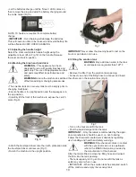
11
before refilling the solution tank.
3 Controls
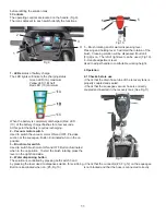
The operating controls are located on the handle. (Fig 9).
The icons adjacent to each switch identify the functions.
1 - LEDs
status of battery charge
The LED lights will indicate the charging status.
Green LED (1A) maximum.
Yellow LED (1B) half
Red LED (1C) minimum
When the battery is completely discharged, (Red LED
(1C) of the battery charger flashes for a few seconds.
At this point the battery requires recharging.
2 – Vacuum motor switch
Used to switch the vacuum motor ON and OFF. Provides
suction at the squeegee. Button illuminated when in the on
position.
3 – Brush motor switch
Used to switch brush motor ON and OFF. Button illuminated
when in the on position. To start the brush rotating press the
lever on the right hand side.
4 – Water dispensing button
The solution is controlled by pressing both switch 3 and
by pressing the lever used to dispense solution for scrubbing.
Button is illuminated when on. (#5, Fig 10)
Fig 9
1
3
2
4
A
C
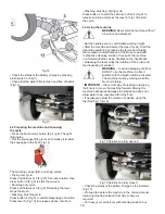
5 – Brush rotating and/or water dispensing lever
Pressing and holding lever 5 will start the rotation of the
brush. Cleaning solution will be dispensed if button 4
(Fig 9) is on. The left of right lever can be used. (Fig 10).
6 - Handle adjustment lever
Used to adjust handle to comfortable working height.
4 Operation
4.1 Checks before use
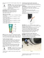
• Check that the drain hose tube of the recovery tank is
properly coupled and sealed.
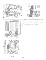
• Check that the squeegee vacuum hose is correctly
coupled and inserted in the recovery tank (See Fig 11).
• Check that the connector (#3, Fig 12) on the squeegee
is not blocked and that the hose is connected correctly.
Fig 11
5
5
6
Fig 10


