MultiMediaCard Product Manual
SanDisk MultiMediaCard Product Manual Rev. 2 © 2000 SANDISK CORPORATION
71
6.4
SPI Bus Timing Diagrams
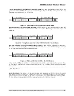
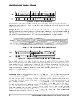
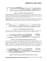
All timing diagrams use the following schematics and abbreviations:
H
Signal is high (logical ‘1’)
L
Signal is low (logical ‘0’)
X
Don’t care
Z
high impedance state (-> = 1)
*
repeater
Busy
Busy Token
Command
Command token
Response
Response token
Data block
Data token
All timing values are defined in Table 6-2. The host must keep the clock running for at least N
CR
clock
cycles after the card response is received. This restrictions applied to command and data response
tokens.
6.4.1
Command/Response
Host Command to Card Response - Card is Ready
Host Command to Card Response - Card is Busy

