MultiMediaCard Product Manual
SanDisk MultiMediaCard Product Manual Rev. 2 © 2000 SANDISK CORPORATION
19
4.0 MultiMediaCard Interface Description
4.1
Physical Description
The MultiMediaCard has seven exposed contacts on one side. (See Figure 2-1.) The host is connected to
the MultiMediaCard using a seven pin connector as shown in the Appendix at the end of this manual.
4.1.1
Pin Assignments in MultiMediaCard Mode
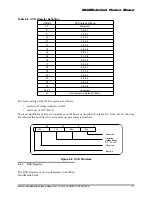
Table 4-1 MultiMediaCard Pad Definition
Pin #
Name
T y p e *
MultiMediaCard Description
1
RSV
NC
Not Connected or Always ‘1’
2
CMD
I/O/PP/OD
Command/Response
3
VSS1
S
Supply voltage ground
4
VDD
S
Supply voltage
5
CLK
I
Clock
6
VSS2
S
Supply voltage ground
7
DAT[0]
I/O/PP
Data 0
*Note: S=power supply; I=input; O=output; PP=push-pull; OD=open-drain; NC=not connected.
4.1.2
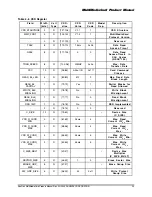
Pin Assignments in SPI Mode
Table 4-2 SPI Pad Definition
Pin #
Name
T y p e *
SPI Description
1
CS
I
Chip Select (Active low)
2
DataIn
I
Host to Card Commands and Data
3
VSS1
S
Supply Voltage Ground
4
VDD
S
Supply Voltage
5
CLK
I
Clock
6
VSS2
S
Supply Voltage Ground
7
DataOut
O
Card to Host Data and Status
*Note: S=power supply; I=input; O=output.
4.2
MultiMediaCard Bus Topology
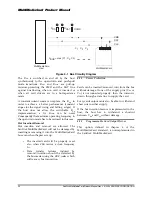
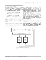
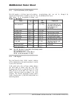
The MultiMediaCard bus has three communication lines and four supply lines:
•
CMD: Command is a bi-directional signal. Host and card drivers are operating in two modes,
open drain and push pull.
•
DAT: Data is a bi-directional signal. Host and card drivers are operating in push pull mode.
•
CLK: Clock is a host to card signal. CLK operates in push pull mode.
•
VDD: VDD is the power supply line for all cards.
•
VSS[1:2]: VSS are two ground lines.


