


S&C Instruction Sheet 695-510
31
Appendix D
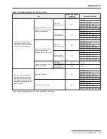
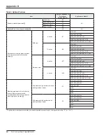
Table 8. Optional Features—Continued
Item
Suffix to be Added to
Switchgear
Catalog Number
Applicable to Models
Parking stands
At all load-interrupter
switches and bus taps
-G1
110
▲
, 312, 413, 514
210, 321, 422, 523, 624
330, 431, 532, 633
440
550
660
At all fault interrupters and
bus taps
-G2
101
▲
, 321, 431
201, 312, 422, 532, 642
303, 413, 523, 633
404, 514, 624
505, 615
606
Reverse color of the
Open / Reset and Closed indicators (i .e ., green for Closed
and red for
Open / Reset indicators)
-J1
All
Potential indication . Indicates presence of voltage on each phase . One indicator
is provided for each load-interrupter switch and fault-interrupter way . Includes
provisions for low-voltage phasing
-L2
110, 101, 210, 201
303, 312, 321, 330
404, 413, 422, 431, 440
505, 514, 523, 532, 541, 550
606, 615, 624, 633, 642, 651, 660
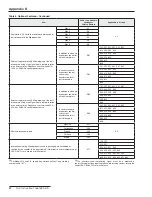
600-ampere bushing adapters
without
studs on all load-interrupter switches,
fault interrupters and bus terminals (in lieu of 600-ampere bushing adapters
with
studs)
-M1
All
200-ampere bushing-well adapters on all fault interrupters and bus taps (in lieu
of 600-ampere bushing adapters) . Interrupting rating of fault interrupters is
12,500 amperes when 200-ampere bushing-well adapters are furnished
-M4
101
●
, 201
★
, 321, 431, 541, 651
312, 422
303, 413, 523, 633
404, 514, 624
505, 615
606
Continuous ground bus . Connects to all load-interrupter switches and fault
interrupters; provides a convenient location to attach cable-concentric neutrals,
separable connector drain wires, and user-provided grounding cables . Short-
circuit rating of ground bus equals that of the switchgear assembly
-O
110, 101, 210, 201
303, 312, 321, 330
404, 413, 422, 431, 440
505, 514, 523, 532, 541, 550
606, 615, 624, 633, 642, 651, 660
Motor operator .
①②
Permits remote operation
of the load-interrupter switch or fault interrupter .
Includes a receptacle for a wired portable remote
control pendant, plus a receptacle for auxiliary
contacts to track the position of the isolating
disconnect . Requires user-furnished
120–240-Vac, 50/60-Hz control power source
Way 1
-B1
All
Way 2
-B2
Way 3
-B3
Way 4
-B4
Way 5
-B5
Way 6
-B6
Auxiliary contacts for way
not
furnished with a
motor operator .
③
Track position of the isolating
disconnect associated with each load-interrupter
switch or fault interrupter
Way 1
-S1
All
Way 2
-S2
Way 3
-S3
Way 4
-S4
Way 5
-S5
Way 6
-S6
①
Order portable remote control pendant, one per switchgear assembly;
see Table 9 on page 33 .
②
For Models 210 and 201, specify motor operator on Way 1 only (cata-
log number suffix “-B1”) .
③
For Models 210 and 201, specify auxiliary contacts on Way 1 only
(catalog number suffix “-S1”) .
▲
Parking stands will only be supplied on the entrance (center) set of
bushings .
●
200-ampere bushing wells will be installed on lower bushings .
★
200-ampere bushing wells will be installed on bus tap bushings .
TABLE CONTINUED
▶