

18
S&C Instruction Sheet 695-510
Operation
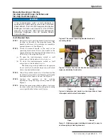
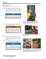
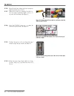
Checking for Voltage Using the Optional Potential
Indication Feature
Figure 29. The Potential Indication feature with
the cover removed.
WARNING
Before using the
Potential Indication feature, always test
for proper operation . If the
Potential Indication feature is
not operating properly, test for voltage using an alternate
method .
NOTICE
The
Potential Indication feature uses a capacitor
voltage divider with a ratio of 2400:1 . A line-to-neutral
voltage of 7 .2 kV will read approximately 3 .0 Vac on
the voltmeter . Accuracy of the
Potential Indication
feature is approxi/-8% .
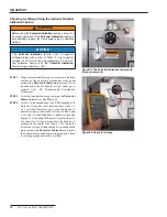
STEP 1.
Using water and mild soap, if necessary, clean the
surface of the operating mechanism front panel
around the
Potential Indication
feature. Petro-
leum-based solvents should not be used on or
around Vista SD Underground Distribution
Switchgear.
STEP 2.
Unscrew the aluminum cap covering the
Potential
Indication
feature. See Figure 29.
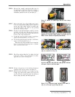
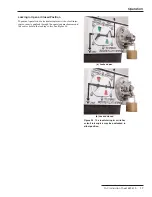
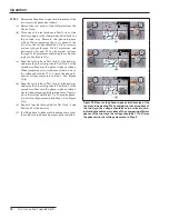
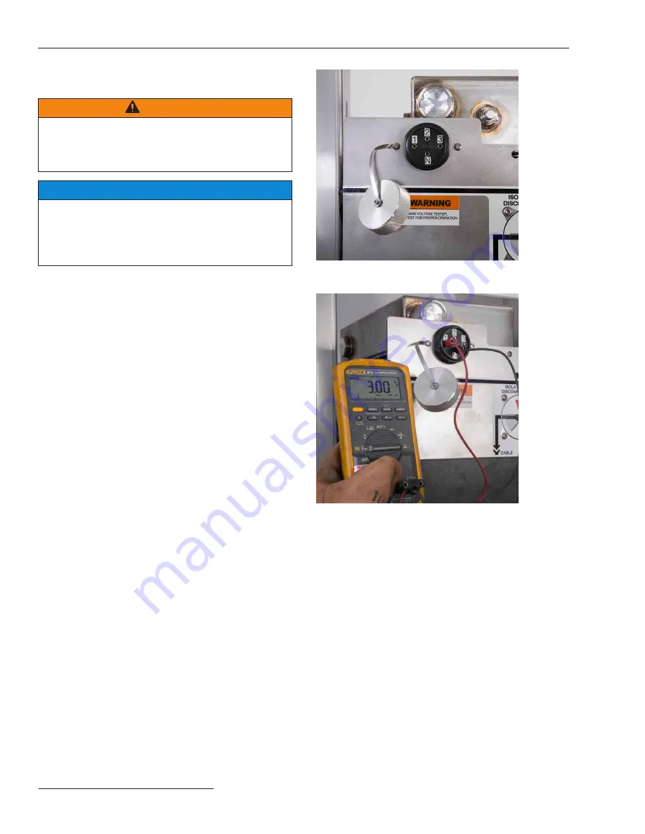
STEP 3.
Attach a high-impedance true RMS-reading volt-
meter, set to read ac volts, between Test Jacks 1, 2,
or 3, and the Neutral Jack to read the phase-to-
neutral voltage, or between Test Jacks 1 and 2, 2 and
3, or 3 and 1, to read the phase-to-phase voltage. See
Figure 30. A reading on the meter greater than 0.5
Vac indicates voltage is present at the bushing. A
reading on the meter less than 0.5 Vac indicates
there is no voltage at the bushing. No reading on the
meter means the
Potential Indication
feature or
the voltmeter may not be operating properly. Check
for voltage using an alternate method.
Figure 30. Check for voltage.