


30
S&C Instruction Sheet 695-510
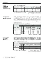
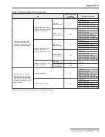
Table 8. Optional Features
Item
Suffix to be Added to
Switchgear
Catalog Number
Applicable to Models
Alternate-color outdoor finish
①
Light gray
-A2
All
Equipment green
-A3
Seafoam green
-A4
Special color
-A5
Hexhead Bolt in lieu of pentahead bolt
①
-H1
All
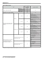
Base spacer with olive green outdoor
finish, increases cable-termination
height
①
Mild steel
6 inches
-K7
210, 201
303, 312, 321, 330
404, 413, 422, 431, 440
505, 514, 523, 532, 541, 550
606, 615, 624, 633, 642, 651, 660
12 inches
-K8
210, 201
303, 312, 321, 330
404, 413, 422, 431, 440
505, 514, 523, 532, 541, 550
606, 615, 624, 633, 642, 651, 660
Stainless steel
6 inches
-K17
210, 201
303, 312, 321, 330
404, 413, 422, 431, 440
505, 514, 523, 532, 541, 550
606, 615, 624, 633, 642, 651, 660
12 inches
-K18
210, 201
303, 312, 321, 330
404, 413, 422, 431, 440
505, 514, 523, 532, 541, 550
606, 615, 624, 633, 642, 651, 660
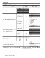
Mounting provisions for fault indicator
for each load-interrupter switch .
Accommodates three-phase indicator
with single-phase sensors
①
Pad-mounted style enclosure with no
viewing window in door
-F1
210, 312, 413, 514
321, 422, 523, 624
330, 431, 633
440
550
660
Pad-mounted style enclosure with
viewing window in door
-F2
210, 312, 413, 514
321, 422, 523, 624
330, 431, 633
440
550
660
①
Applicable to switchgear assemblies with a pad-mounted-style enclosure (catalog number suffix “-P1” or “-P11”) .
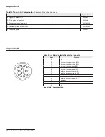
Appendix D