26
/
56
Chapter 7 VMR-I Cable Connection
This chapter describes how the signal and power cables of the VMR-I HD Series are
connected.
7.1 VMR-I
HD series product cabinet interface introduction
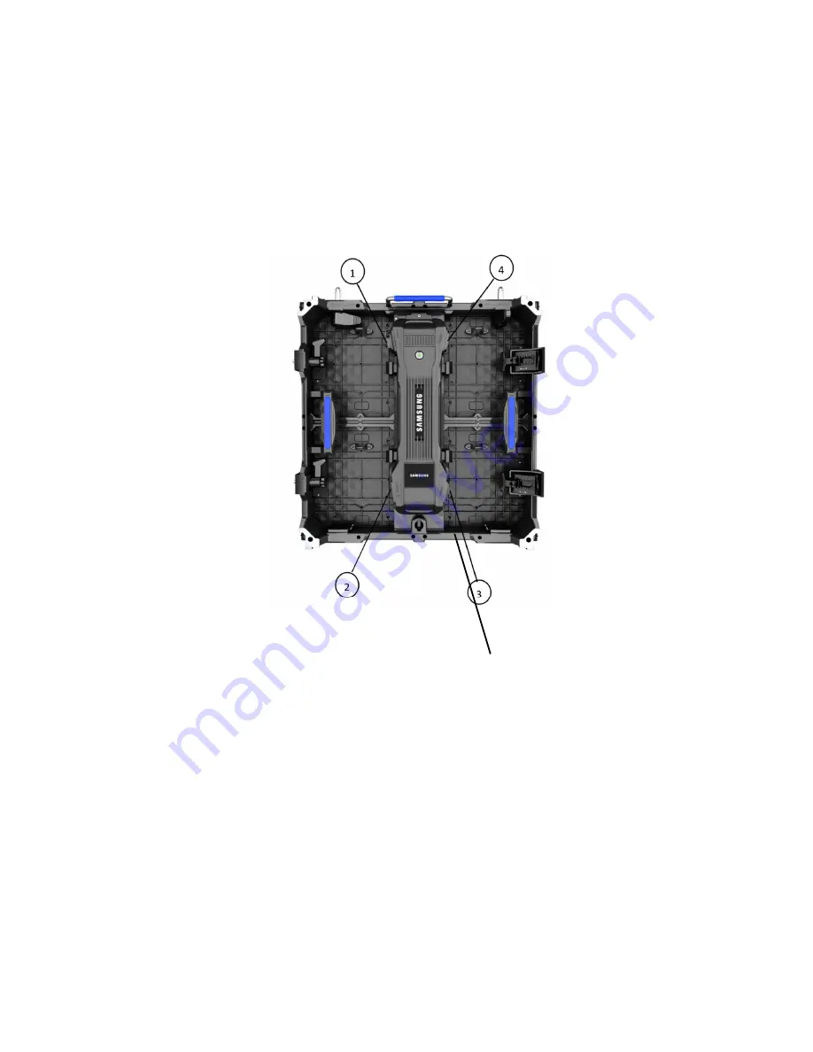
Picture 7-1 VMR-I Cabinet Connection Port
①
Power Output
②
Power Input
③
Signal Output/Input
④
Signal Output/Input
Note: The Seetronic head is used for the 1-4 interface. All electrical parameters refer
to its specifications.
①
、
②
power interfaces are strictly differentiated between input and output. When
cascaded, the output interface of the cabinet is connected to the next cabinet input.
③
、
④
signal interface is the RJ45 interface. These two interfaces are independent of
input and output. After the signal is connected, the system receiving card will
automatically recognize the signal input or input.
7.2 Power Cord Connection


