E-
23
ENGLISH
Testing operations
1
Check the power supply between the outdoor unit and the auxiliary circuit
breaker.
Single phase power supply: L, N
2
Check the indoor unit.
2-1 Check that you have connected the power and communication
cables correctly. (If the power cable and communication cables one
mixed up or connected incorrectly, the PCB will be damaged.)
2-2 Check the thermistor sensor, drain pump/hose, and display are
connected correctly.
3
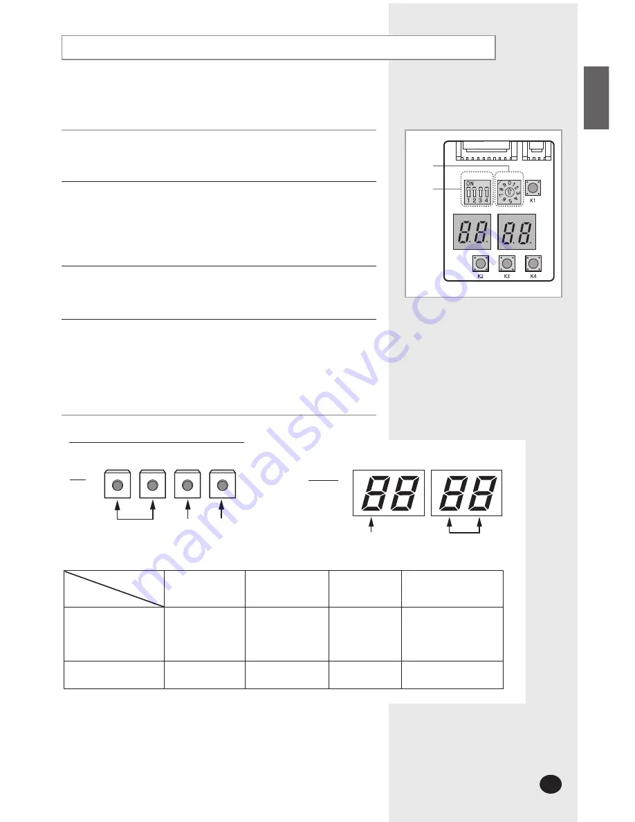
Press K1 & K2 on the outdoor unit PCB the system will follow this sequence:
K1 push one
start Heating test mode
K1 push two
test mode stop
K2 push one
start Cooling test mode
K2 push two
test mode stop
4
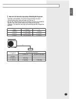
After 12 minutes of stationary condition check each indoor unit air treatment :
Cooling mode(indoor unit check)
Inlet air temp. - Outlet air temp. :
From
50°F(10°C) to 53.6°F(12°C)
Heating mode(indoor unit check)
Outlet air temp. - Inlet air temp. :
From
51.8°F(11°C) to 57.2°F(14°C)
In heating mode, the indoor fan motor can remain off to avoid cold air
blown into conditioned space.
Settings of PCB Display of the Outdoor unit
K1
K3
K2
CHECK
MODE
DISPLAY
MODE
RESET
K4
DIS 1
DIS 2
Display
KEY
ITEM NO.
CURRENT DATA DISPLAY
Number of
press times
K1
K2
K3
K4
1
Test operation at
heating mode
Test operation at
cooling mode
Reset
Displays Data
2
End
End
-
-
Function
����
����
����
����
DIP
Switch
Rotary
Switch
Note
Rotary Switch must be adjusted to"0"position .
DIP Switch must be adjusted to "ON" position .
Summary of Contents for UH070CAV1
Page 26: ......

