background image

E-

16

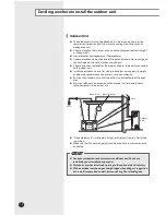
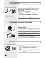
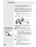
Performing leak tests

Insulation

No gap

NBR(T

0.511inch

 or thicker)

Connecting the drain hose to the outdoor unit

B

A

  The designs and shape are subject to 

change according to the model.

LEAK TEST WITH NITROGEN (before opening valves)

In order to detect basic refrigerant leaks, before recreating the vacuum  
and recirculating the R410A, it’s responsable of installer to pressurize the whole 
system with nitrogen (using a cylinder with pressure reducer) at a pressure 
above 30 bar (gauge).

LEAK TEST WITH R410A (after opening valves)

Before opening valves, discharge all the nitrogen into the system and create 
vacuum. After opening valves check leaks using a leak detector for  
refrigerant R410A.
Once you have completed all the connections, check for possible leaks using 
leak detector specifically designed for HFC refrigerants.

To check for gas leaks on the...

Then, using a leak detector, 
check the...

Outdoor unit

Valves on sections A and B.

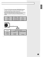
When using the air conditioner in the heating mode, ice may accumulate . 
During de-icing (defrost operation), the condensed water must be drained off 
safely. Consequently, you must install a drain hose on the outdoor unit,  
following the instructions below.

1

Make space more than 

1.97inch(50mm)


between the bottom of the outdoor 

unit and the ground for installation of the drain hose, as shown in figure.

2

Insert the drain plug into the hole on the underside of the outdoor unit.

3

Connect the drain hose to the drain plug.

4

Ensure that the drained water runs off correctly and safely.

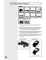
Once you have checked that there are no leaks in the system, you can insulate 
the piping and hose.

1

To avoid condensation problems, place an insulator around each  

refrigerant pipe.

Note


  When insulate the pipe, be sure to overlap the insulation.  


   You have to use more than 

248°F(120°C)


insulation(

T0.511inch(13

mm)

 or thicker Acrylonitrile Butadien Rubber) for the gas refriger-

ant pipe.

1.97inch(50mm)

1.18inch(30mm)

Summary of Contents for UH070CAV1

Page 1: ...ENGLISH INSTALLATION MANUAL UH070CAV1 UH105CAV UH140CAV ESPA OL FRAN AIS System Air Conditioner Cooling and Heating S E F DB98 29516A 3...

Page 2: ...l these operations may cause electric shocks or fires Do not place containers with liquids or other objects on the unit All the materials used for the manufacture and packaging of the air conditioner...

Page 3: ...ecting the refrigerant pipe 13 Connecting up and removing air in the circuit 14 Cutting Flaring the pipes 15 Performing leak tests 16 Connecting the drain hose to the outdoor unit 16 Insulation 16 Usi...

Page 4: ...AV Heat pump Preparation for outdoor unit installation The air conditioner uses R410A refrigerant 690 932 78 375 8 2 1 1 2 6 1 1 6 6 9 3 0 4 7 2 4 6 3 0 1 4 12 610 50 12 880 52 9 364 17 6 312 6 796 5...

Page 5: ...byWire Rope Fasten the outdoor unit by two 8m or longer wire ropes as shown at the figure To prevent from damage or scratches insert a piece of cloth between the outdoor unit and rope then move the un...

Page 6: ...position that enables the pipes and cables to be easily connected to the indoor unit Install the outdoor unit on a flat stable surface that can support its weight and does not generate any unnecessar...

Page 7: ...are blocked by the wall 1500 or more 2000 or more The upper part of the outdoor unit and the air outlet is towards the wall 600 or more 300 or more The upper part of the outdoor unit and the air outle...

Page 8: ...re blocked by the wall When front and rear side of the outdoor unit is towards the wall When front and rear side of the outdoor unit is towards the wall When installing more than 1 outdoor unit Our un...

Page 9: ...t is installed on the roof you have to check the ceiling strength and waterproof the unit CAUTION Outdoor Unit Support Anchor bolt Outdoor Unit Base Surface Outdoor Unit Support OUTDOOR UNIT INSTALLED...

Page 10: ...t Communication cable Grounding Power cable Communication cable When using ELB for 1 phase If an outdoor unit is installed in a place in danger of an electric leak or submergence you must install the...

Page 11: ...eatly it may shorten the life of the condenser If the unbalanced power is exceeded over 4 of supply rating the indoor unit is protected stopped and the error mode indicates To protect the product from...

Page 12: ...ect the rated cables only Connect using a driver which is able to apply the rated torque to the screws If the terminal is loose fire may occur caused by arc If the terminal is connected too firmly the...

Page 13: ...allowable length Actual pipe length L0 H L1 164 04ft 50m or less 246 06ft 75m or less Allowable height length Actual pipe length H 98 43ft 30m or less 98 43ft 30m or less Minimum pipe length equal or...

Page 14: ...PEN position of Electronic Expansion Valve EEV 4 Open the valve of the low pressure side of manifold gauge counterclockwise 5 Purge the air from the system using vacuum pump for about 10 minutes Close...

Page 15: ...0 086 inch 19 05 mm 3 4 0 086 inch 5 Check that the flaring is correct referring to the illustrations below for examples of incorrect flaring Inclined Damaged Surface Cracked UnevenThickness 6 Align...

Page 16: ...using a leak detector check the Outdoor unit Valves on sections A and B When using the air conditioner in the heating mode ice may accumulate During de icing defrost operation the condensed water mus...

Page 17: ...ply excessive force to the stop valve and always use special instruments Otherwise the stopping box can be damaged and the back sheet can leaks If the watertight sheet leaks turn the axis back by half...

Page 18: ...user if system contains 6 6lb 3kg or more of fluorinated green house gases In this case it has to be checked for leakage at least once every 12 months according to regulation n 842 2006 This activity...

Page 19: ...the outdoor unit situation before adding refrigerant This operation can only be performed by a qualified refrigeration specialist How to Calculate the Quantity of Adding Refrigerant Model Q R410A P UH...

Page 20: ...between the transmitter and the outdoor unit refer to the figure of page 20 3 If you install a transmitter to an outdoor unit every indoor unit which is connected to an outdoor unit can be controlled...

Page 21: ...onditioner Refer to this procedure when the unit is relocated Carry out the pump down procedure refer to the details of pump down Remove the power cord Disconnect the assembly cable from the indoor an...

Page 22: ...least two metres away from a lightening conductor grounding electrode and its cable Note The grounding wire for the telephone line cannot be used to ground the air conditioner 3 Finish wrapping insula...

Page 23: ...ooling test mode K2 push two test mode stop 4 After 12 minutes of stationary condition check each indoor unit air treatment Cooling mode indoor unit check Inlet air temp Outlet air temp From 50 F 10 C...

Page 24: ...pipe has been dis mounted Operation off Indoor Sensor Error Secondary detection of indoor floating switch Check the indoor unit s float sensor Check the indoor PCB connector CN51 black Operation off...

Page 25: ...eck refrigerant is filled Check the connection status of compressor and if it operates normally Check for any obstacles around indoor outdoor units Operation off Outdoor unit pro tection control error...

Page 26: ......
Reviews: