CIRCUIT DESCRIPTION
2. operation description
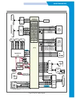
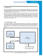
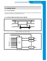
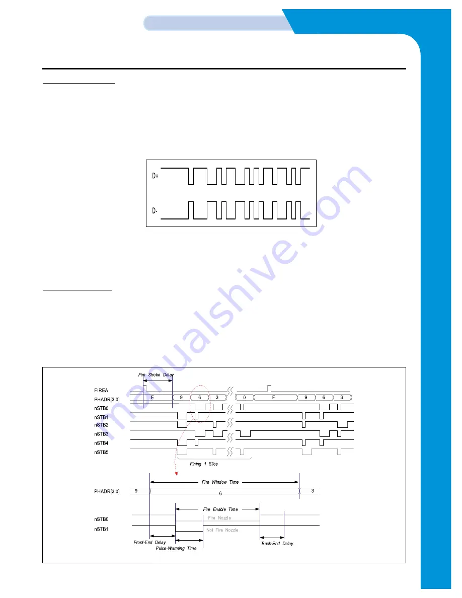
This system, when Host and USB cables are connected, and when +5V is detected in power detector inside chip and Vbus,
3.3V comes out through Pull-uP terminal. This is also connected to DP in pattern of hardware and supports Full-speed. Utilizing
Configuration Endpoint, EPO, in USB controller, Plug & Play function is operated. Exchange of information between PCs is
accomplished through DP and DM erminals. This terminal decides transmission speed depending on connection of regulator
output in USB controller, and decides size of signal following USB and SPFC. Signal of general DP and DM terminals are same
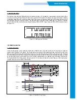
as Figure 10-3.
<8> HEAD Control Part
1. General Information
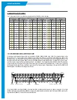
It drives the Inkjet Head, and it controls the HA[3:0] and _STB[5:0], which control the Six-Shooter. The Six-shooter creates the
signal to drive 48 Nozzle of the HEAD. The Stubby Head in the system is the Bubble type head, and has 48 nozzle for the
Mono and Color(Printer only). 48 Nozzle Head of the mono and color head receives the data by 6 bytes per1 slice. The data
from the HDMA goes to the CDE (Consecutive Dot Eliminator), DITH, and Data Out Block, and the data and address, controlled
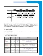
by the Fire signal and the Fire Window Time of the CRCON_CRFIRE Block, are outputted to the head Driver (Six-Shooter).
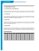
The head consists of the 4 firing groups. Each group has 12~14 nozzles, and only one nozzle is firing per a Fire in each group.
It means that one Fire can make 4 nozzles firing.
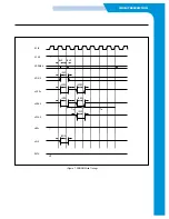
< Figure 10-3. USB Signal Line DIAGRAM >
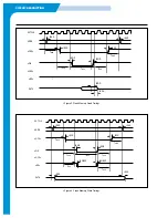
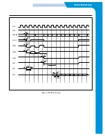
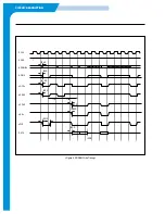
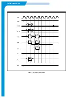
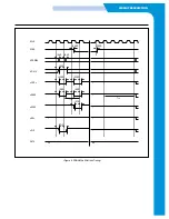
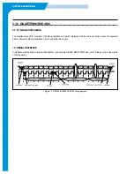
< Figure 12. Print48(HP) Firing Timing >
Summary of Contents for SF-335T
Page 2: ......
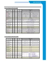
Page 19: ...CIRCUIT DESCRIPTION 2 Chorus 2 Assigned GPO Ports for RHINE ...
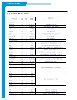
Page 21: ...CIRCUIT DESCRIPTION 5 HP IMPORTANT ASIC Ports for RHINE ...
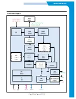
Page 24: ...CIRCUIT DESCRIPTION 3 1 5 3 Block Diagram Figure 16 Block Diagram of IP_TOP ...
Page 35: ...CIRCUIT DESCRIPTION 3 1 8 6 FM214 MODEM BLOCK DIAGRAM 3 1 8 7 FM214 VS MODEM BLOCK DIAGRAM ...
Page 36: ...CIRCUIT DESCRIPTION 3 1 8 8 FM214 SERIES MODEM PIN DESCRIPTION ...
Page 48: ...4 5 Samsung Electronics SCHEMATIC DIAGRAMS Repair Manual 4 2 LIU Circuit Diagram 2002 06 25 ...

