CIRCUIT DESCRIPTION
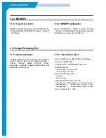
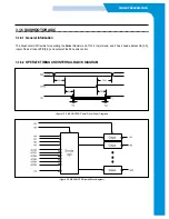
3.1.5.1 General description
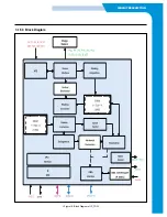
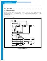
The image processor, built-in to Chorus-2 is consisted of
Scanner Interface, Motor control, Shading Acquisition _
Shading Correction, Gamma Correction, Vertical
Decimation, Horizontal Enlargement/Decimation and
Binarization. (See Figure 16)
3.1.5.2 Features & Functions
• 0.18µm CMOS process, 208-pin QFP, std 130 library
• Frequency : 66MHz(15ns)
• Image Sensor I/F : 200/300/600dpi CIS or CCD
• Scanning Function
-
Color Gray Image : each 8 bits / RGB
- Mono Gray Image : 8 bits / pixel
• Maximum processing Width
-
A4, 600 dpi
- 5KB Effective pixel
• Ideal MSLT (Minimum Scan Line Time)
-
Grey mode(Color) : 3(RGB) X 5KB X 15nsec X 16clock =3.69 msec
- Grey mode(mono) : 1 X 5KB X 15nsec X 16clock =1.23 msec
- Grey mode(Color) : 1 X 5KB X 15nsec X 16clock =1.23 msec
• A/D conversion depth : 10 bits
3.1.4.1 General description
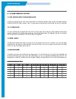
MEMORY applied in this system are FLASH MEMORY(U7)
of 1Mbyte, SDRAM (SF-330/331P:U9 ; 2Mbyte ,/ SF-335T
: U8 ; 8Mbyte)
3.1.4.2 MEMORY configuration
By each CHIP SELECT (
ROM_CS, _SCS0, _SD_RAS
,_SD_CAS ), FLASH MEMORY and SDRAM are selected,
and DATA is accessed by HALF WORD unit.
3.1.4 MEMORY
3.1.5 Image Processing Part
Summary of Contents for SF-335T
Page 2: ......
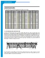
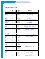
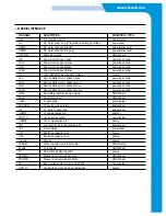
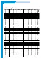
Page 19: ...CIRCUIT DESCRIPTION 2 Chorus 2 Assigned GPO Ports for RHINE ...
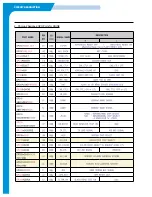
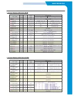
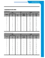
Page 21: ...CIRCUIT DESCRIPTION 5 HP IMPORTANT ASIC Ports for RHINE ...
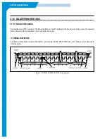
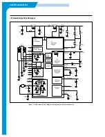
Page 24: ...CIRCUIT DESCRIPTION 3 1 5 3 Block Diagram Figure 16 Block Diagram of IP_TOP ...
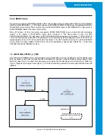
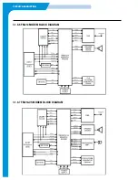
Page 35: ...CIRCUIT DESCRIPTION 3 1 8 6 FM214 MODEM BLOCK DIAGRAM 3 1 8 7 FM214 VS MODEM BLOCK DIAGRAM ...
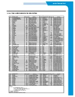
Page 36: ...CIRCUIT DESCRIPTION 3 1 8 8 FM214 SERIES MODEM PIN DESCRIPTION ...
Page 48: ...4 5 Samsung Electronics SCHEMATIC DIAGRAMS Repair Manual 4 2 LIU Circuit Diagram 2002 06 25 ...

