4-15
Samsung Electronics
Summary of product
Service Manual
6) Feature
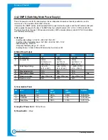
- Insulation resistance : over 50M
Ω
(at DC500V)
- Insulation retest pressure : Must be no problem within 1min. (at 1500Vzc, 10mA)
- Leakage voltage : under 3.5mA
- Running voltage : under 40A peak (at 25°c, Cold start) Under 60A peak (in other conditions)
- Rise Time : Within 2Sec
- Fall Time : Over 20ms
- Surge : Ring Wave 6KV-500A (Normal, Common)
7) Environment Condition
- Operating temperature range : 0°c ~ 40°c
- Storage temperature range : -25°c ~ 85°c
- Storage humidity range : 30% ~ 90% RH
- Operating atmospheric pressure range : 1
8) EMI Requirement :
CISPR ,FCC, CE, MIC, C-Tick,
9) Safty Requrement
- IEC950 UL1950, CSA950, C-UL,Semko,iK,CB, CCC(CCIB),GOST, EPA,
4.4.3 Fuser AC Power Control
The Fuser (HEAT LAMP) is heated using AC power. The AC power is controlled by a Triac (THY1), a semiconductor
switch. 'On/Off control' is achieved when the gate of the Triac is turned on/off by a Photo triac (PC1), this is an
insulting part.
In the other words the AC control part is a passive circuit. It turns the heat lamp on/off by taking a signal from the
engine control section. When the 'HEATER ON' signal is activated by the engine the LED of PC1 (Photo Triac)
flashes. The flashing light causes the Triac (PC1) to switch and a voltage is supplied to the gate of Triac THY1.
As a result AC current flows in the heat lamp, and heat is produced. On the other hand, when the signal is off,
PC1 is off, the voltage is cut off at the gate of Triac THY1, this Triac is therefore off, and thus the heat lamp is
turned off.
1) Triac (THY1) feature
- 12A,600V SWITCHING
2) Phototriac Coupler (PC3)
- Turn On If Current : 15mA ~ 50mA(Design: 16mA)
- High Repetive Peak Off State Voltage : Min 600V
Summary of Contents for scx-4100 series
Page 13: ...2 6 Reference Information Samsung Electronics Service Manual 2 4 2 A4 2 Pattern ...
Page 14: ...2 7 Samsung Electronics Reference Information Service Manual 2 4 3 A4 IDC 5 Patten ...
Page 15: ...2 8 Reference Information Samsung Electronics Service Manual MEMO ...
Page 21: ...3 6 Specifications Samsung Electronics Service Manual MEMO ...
Page 23: ...4 2 Summary of Product Samsung Electronics Service Manual 4 1 2 Rear View ...
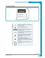
Page 24: ...4 3 Samsung Electronics Summary of product Service Manual 4 1 3 Control Panel ...
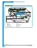
Page 25: ...4 4 Summary of Product Samsung Electronics Service Manual 4 2 System Layout SCAN PART ...
Page 39: ...4 18 Summary of Product Samsung Electronics Service Manual MEMO ...
Page 57: ...5 18 Disassembly and Reassembly Samsung Electronics Service Manual MEMO ...
Page 93: ...7 28 Troubleshooting Samsung Electronics Service Manual MEMO ...
Page 110: ...9 9 9 1 Samsung Electronics Block Diagram Service Manual 9 Block Diagram ...


