77
TROUBLE SHOOTING
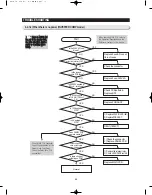
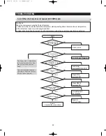
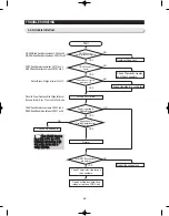
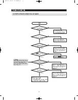
4-2-10) When Water Tank Heater does not operate
Start
MAIN PCB is normal.
-- Check other parts.
Check Water Tank Heater Wire.
Check if the Heater is open.
- Check Power Plug
- Check Main Fuse (Blown)
- Check Wire Connections
NO
Do Forced Operation and
check it again with Comp on.
NO
Check if IC11(S3P84E9-
LOAD MICOM) #37 is 5V.
If it is 0V, replace MAIN
PCB.
NO
Replace
RY79
Relay
NO
If it is 0 , check if Heater is short.
If it is
, check if there is wire-cut,
Heater is open or the connector is
slipped out.
If it is 0 , check if Heater is short.
If it is
, check if there is wire-cut,
Heater is open or the connector is
slipped out.
NO
NO
YES
YES
YES
YES
YES
YES
The refrigerator
operates normally.
Comp is operating.
5V is applied at MAIN
PCB IC74 #6.
RY79
AC terminals
are on.
There is a
resistance read at CN71#5
and CN70 #9.
The reading is
15~17K .
Caution
Before reading the resistances, plug
out the unit. Then, plug out the
connect from MAIN PCB and read
them at the wires.
Summary of Contents for RSJ1K Series
Page 2: ......
Page 68: ...TROUBLE SHOOTING SPM FREEWHEELING DIODE Voltage 68...
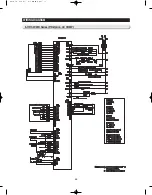
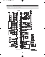
Page 82: ...82 6 WIRING DIAGRAM 6 1 RS21 23H Series CHINA Z Option Inverter COMP...
Page 83: ...83 WIRING DIAGRAM 6 2 RS21 23H Series CHINA V S Option Inverter COMP...
Page 84: ...84 WIRING DIAGRAM 6 3 RS21 23H Series Z Y Option Inverter COMP...
Page 85: ...85 WIRING DIAGRAM 6 4 RS21 23H Series P U Option Inverter COMP...
Page 86: ...86 WIRING DIAGRAM 6 5 RS21 23H Series V S Option Inverter COMP...
Page 87: ...87 WIRING DIAGRAM 6 6 RS21 23H Series K J Option AC COMP...
Page 88: ...88 WIRING DIAGRAM 6 7 RS21 23H Series F D Option AC COMP...
Page 89: ...89 WIRING DIAGRAM 6 8 RS21 23H Series B N Option AC COMP...
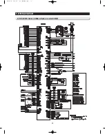
Page 90: ...90 WIRING DIAGRAM 6 9 RSJ1 Series Z Option Inverter COMP...
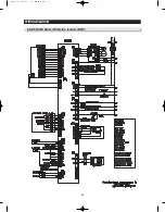
Page 91: ...91 WIRING DIAGRAM 6 10 RSJ1 Series P Option Inverter COMP...
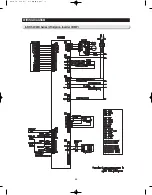
Page 92: ...92 WIRING DIAGRAM 6 11 RSJ1 Series K J Option AC COMP...
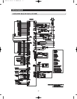
Page 93: ...93 WIRING DIAGRAM 6 12 RSJ1 Series F D Option AC COMP...
Page 94: ...94 94 7 SCHEMATIC DIAGRAM 7 1 Main PCB Schematic Diagram RSJ1 Series...
Page 95: ...95 95 SCHEMATIC DIAGRAM 7 2 Main PCB Schematic Diagram RS21 23H Series...
Page 96: ...96 SCHEMATIC DIAGRAM 7 3 Inverter PCB Schematic Diagram RSJ1 RS21 23H Series...
Page 97: ...97 SCHEMATIC DIAGRAM 7 3 1 BLOCK DIAGRAM RS21 23H Series All...
Page 98: ...98 SCHEMATIC DIAGRAM 7 3 2 BLOCK DIAGRAM RS21 23H Series Inverter COMP...
Page 99: ...99 SCHEMATIC DIAGRAM 7 3 3 BLOCK DIAGRAM RS21 23H Series AC COMP...
Page 100: ...8 REFERENCE INFORMATION Label Location 8 1 RSJ1 Series Nomenclature 100...
Page 101: ...101 REFERENCE INFORMATION Label Location 8 2 RS21 23H Series Nomenclature...
Page 106: ...106 REFERENCE INFORMATION 8 6 Air Circulation...

