5
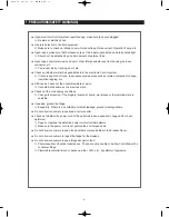
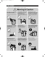
1. PRECAUTIONS(SAFETY WARNINGS)
Upon electronic Control system repair/change, make sure the set unplugged.
Be ware of electric shock.
Use rated electronic Control equipment.
Make sure to check out ModeL name, Rated voltage, Rated current, Operation Temp, etc.
Upon repair, make sure that harnesses are not to be water-penetrated and are bundled tight.
Should not be detached by a certain amount of external force.
Upon repair, completely remove dust or other foreign substances from housing, harness,
connector, etc.
To prevent fire by tracking, short, etc.
Check out whether water has penetrated into the electronic Control system.
If there is any kind of trace, take necessary measures such as related component change,
insulation tapping, etc.
After repair, check out the assembled state of parts.
It should be the same as the previous state.
Check out the surrounding conditions.
Change the location, if the fridge is located at humid, wet places or the installed state is
unstable.
If needed, ground the fridge.
Especially, if there is a possibility of electric leakage, ground is indispensable.
Do not allow consumers to overload a certain outlet.
Check out whether the power cord or the outlet is broken, squeezed, chopped off or heat-
deformed.
Repair or replace the defective power cord/outlet immediately.
Make sure the power cord is not punctuated or stomped down.
Do not allow consumers to keep food unstable or place bottles in the Freezer Room.
Do not allow consumers to repair the fridge for themselves.
Do not allow consumers to keep things except for food.
Pharmaceutical, Chemical substances : These are not possible to be fine-Controlled with a
consumer fridge.
Flammable material (alcohol, benzene, ether, LPG, etc) : possibility of explosion.
Summary of Contents for RSJ1K Series
Page 2: ......
Page 68: ...TROUBLE SHOOTING SPM FREEWHEELING DIODE Voltage 68...
Page 82: ...82 6 WIRING DIAGRAM 6 1 RS21 23H Series CHINA Z Option Inverter COMP...
Page 83: ...83 WIRING DIAGRAM 6 2 RS21 23H Series CHINA V S Option Inverter COMP...
Page 84: ...84 WIRING DIAGRAM 6 3 RS21 23H Series Z Y Option Inverter COMP...
Page 85: ...85 WIRING DIAGRAM 6 4 RS21 23H Series P U Option Inverter COMP...
Page 86: ...86 WIRING DIAGRAM 6 5 RS21 23H Series V S Option Inverter COMP...
Page 87: ...87 WIRING DIAGRAM 6 6 RS21 23H Series K J Option AC COMP...
Page 88: ...88 WIRING DIAGRAM 6 7 RS21 23H Series F D Option AC COMP...
Page 89: ...89 WIRING DIAGRAM 6 8 RS21 23H Series B N Option AC COMP...
Page 90: ...90 WIRING DIAGRAM 6 9 RSJ1 Series Z Option Inverter COMP...
Page 91: ...91 WIRING DIAGRAM 6 10 RSJ1 Series P Option Inverter COMP...
Page 92: ...92 WIRING DIAGRAM 6 11 RSJ1 Series K J Option AC COMP...
Page 93: ...93 WIRING DIAGRAM 6 12 RSJ1 Series F D Option AC COMP...
Page 94: ...94 94 7 SCHEMATIC DIAGRAM 7 1 Main PCB Schematic Diagram RSJ1 Series...
Page 95: ...95 95 SCHEMATIC DIAGRAM 7 2 Main PCB Schematic Diagram RS21 23H Series...
Page 96: ...96 SCHEMATIC DIAGRAM 7 3 Inverter PCB Schematic Diagram RSJ1 RS21 23H Series...
Page 97: ...97 SCHEMATIC DIAGRAM 7 3 1 BLOCK DIAGRAM RS21 23H Series All...
Page 98: ...98 SCHEMATIC DIAGRAM 7 3 2 BLOCK DIAGRAM RS21 23H Series Inverter COMP...
Page 99: ...99 SCHEMATIC DIAGRAM 7 3 3 BLOCK DIAGRAM RS21 23H Series AC COMP...
Page 100: ...8 REFERENCE INFORMATION Label Location 8 1 RSJ1 Series Nomenclature 100...
Page 101: ...101 REFERENCE INFORMATION Label Location 8 2 RS21 23H Series Nomenclature...
Page 106: ...106 REFERENCE INFORMATION 8 6 Air Circulation...


