


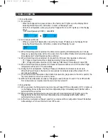


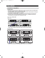


3) Test Cancellation Mode
3-1) During the F/R-Defrost mode, put the Display Panel to the Test mode and press the Fridge button
once. Then, the F/R-Defrost mode will be cancelled and it will go to the normal operation mode.
Or, turn off and on the unit to cancel the Test mode.
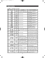
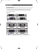
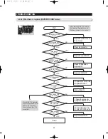
1) Communication Error between MAIN MICOM and Load MICOM
1-1) When there is no response in 10 seconds after the Main MICOM sends a communication signal
to the Load MICOM, "LC Er" will blink on the Display Panel until the communication error is
released.
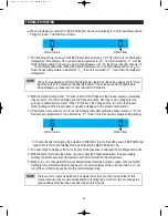
1-2) When there is no response in 10 seconds after the Main MICOM sends a communication signal
to the Load MICOM, the entire Cool Select Zone Display Panel will blink until the communication
error is cancelled (0.5 sec On and 1.5 sec Off).
TROUBLE SHOOTING
4-1-2) Communication Error Display Function
50
Summary of Contents for RSJ1K Series
Page 2: ......
Page 68: ...TROUBLE SHOOTING SPM FREEWHEELING DIODE Voltage 68...
Page 82: ...82 6 WIRING DIAGRAM 6 1 RS21 23H Series CHINA Z Option Inverter COMP...
Page 83: ...83 WIRING DIAGRAM 6 2 RS21 23H Series CHINA V S Option Inverter COMP...
Page 84: ...84 WIRING DIAGRAM 6 3 RS21 23H Series Z Y Option Inverter COMP...
Page 85: ...85 WIRING DIAGRAM 6 4 RS21 23H Series P U Option Inverter COMP...
Page 86: ...86 WIRING DIAGRAM 6 5 RS21 23H Series V S Option Inverter COMP...
Page 87: ...87 WIRING DIAGRAM 6 6 RS21 23H Series K J Option AC COMP...
Page 88: ...88 WIRING DIAGRAM 6 7 RS21 23H Series F D Option AC COMP...
Page 89: ...89 WIRING DIAGRAM 6 8 RS21 23H Series B N Option AC COMP...
Page 90: ...90 WIRING DIAGRAM 6 9 RSJ1 Series Z Option Inverter COMP...
Page 91: ...91 WIRING DIAGRAM 6 10 RSJ1 Series P Option Inverter COMP...
Page 92: ...92 WIRING DIAGRAM 6 11 RSJ1 Series K J Option AC COMP...
Page 93: ...93 WIRING DIAGRAM 6 12 RSJ1 Series F D Option AC COMP...
Page 94: ...94 94 7 SCHEMATIC DIAGRAM 7 1 Main PCB Schematic Diagram RSJ1 Series...
Page 95: ...95 95 SCHEMATIC DIAGRAM 7 2 Main PCB Schematic Diagram RS21 23H Series...
Page 96: ...96 SCHEMATIC DIAGRAM 7 3 Inverter PCB Schematic Diagram RSJ1 RS21 23H Series...
Page 97: ...97 SCHEMATIC DIAGRAM 7 3 1 BLOCK DIAGRAM RS21 23H Series All...
Page 98: ...98 SCHEMATIC DIAGRAM 7 3 2 BLOCK DIAGRAM RS21 23H Series Inverter COMP...
Page 99: ...99 SCHEMATIC DIAGRAM 7 3 3 BLOCK DIAGRAM RS21 23H Series AC COMP...
Page 100: ...8 REFERENCE INFORMATION Label Location 8 1 RSJ1 Series Nomenclature 100...
Page 101: ...101 REFERENCE INFORMATION Label Location 8 2 RS21 23H Series Nomenclature...
Page 106: ...106 REFERENCE INFORMATION 8 6 Air Circulation...


