


69
TROUBLE SHOOTING
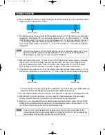
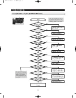
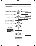
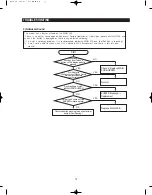
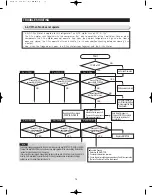
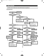
4-2-3) Unable to Defrost
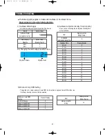
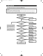
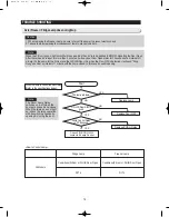
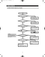
F/D-SEN:Read Resistance between CN30 4 and 9
R/D-SEN:Read Resistance between CN30 10 and 9
F-DEF:Read Resistance between CN70 7 and 3
R-DEF:Read Resistance between CN70 5 and 3
F-SEN:Read Resistance between CN30 3 and 9
R-SEN:Read Resistance between CN30 7 and 9
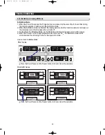
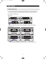
Press the Power Freeze and the Fridge buttons at
the same time for 8 sec. Then, the 2nd Test mode.
Defrost Sensor Voltage is lower than 3.1V
Start
Forced F/R Defrost
Check all the sensors
Normal
Check Thermistor, Heater and
their contacts.
Replace the sensor
NO
Repair the connectors
NO
YES
YES
F/R-DEF Sensor is
normal (with Self Diagnosis)
Check Thermistor, Heater
and their connectors
NO
YES
F/R-DEF Heater is
normal
Forced Operation for a certain time
NO
YES
NO
NO
Defrost Sensor Temp is
lower than -5°C
Power is applied to
Defrost Heater
Repair or Replace defective
relays, or replace PCB Ass'y
MAIN PCB connectors
are normal
YES
YES
It goes back to
Cooling Operation after
heating
Summary of Contents for RSJ1K Series
Page 2: ......
Page 68: ...TROUBLE SHOOTING SPM FREEWHEELING DIODE Voltage 68...
Page 82: ...82 6 WIRING DIAGRAM 6 1 RS21 23H Series CHINA Z Option Inverter COMP...
Page 83: ...83 WIRING DIAGRAM 6 2 RS21 23H Series CHINA V S Option Inverter COMP...
Page 84: ...84 WIRING DIAGRAM 6 3 RS21 23H Series Z Y Option Inverter COMP...
Page 85: ...85 WIRING DIAGRAM 6 4 RS21 23H Series P U Option Inverter COMP...
Page 86: ...86 WIRING DIAGRAM 6 5 RS21 23H Series V S Option Inverter COMP...
Page 87: ...87 WIRING DIAGRAM 6 6 RS21 23H Series K J Option AC COMP...
Page 88: ...88 WIRING DIAGRAM 6 7 RS21 23H Series F D Option AC COMP...
Page 89: ...89 WIRING DIAGRAM 6 8 RS21 23H Series B N Option AC COMP...
Page 90: ...90 WIRING DIAGRAM 6 9 RSJ1 Series Z Option Inverter COMP...
Page 91: ...91 WIRING DIAGRAM 6 10 RSJ1 Series P Option Inverter COMP...
Page 92: ...92 WIRING DIAGRAM 6 11 RSJ1 Series K J Option AC COMP...
Page 93: ...93 WIRING DIAGRAM 6 12 RSJ1 Series F D Option AC COMP...
Page 94: ...94 94 7 SCHEMATIC DIAGRAM 7 1 Main PCB Schematic Diagram RSJ1 Series...
Page 95: ...95 95 SCHEMATIC DIAGRAM 7 2 Main PCB Schematic Diagram RS21 23H Series...
Page 96: ...96 SCHEMATIC DIAGRAM 7 3 Inverter PCB Schematic Diagram RSJ1 RS21 23H Series...
Page 97: ...97 SCHEMATIC DIAGRAM 7 3 1 BLOCK DIAGRAM RS21 23H Series All...
Page 98: ...98 SCHEMATIC DIAGRAM 7 3 2 BLOCK DIAGRAM RS21 23H Series Inverter COMP...
Page 99: ...99 SCHEMATIC DIAGRAM 7 3 3 BLOCK DIAGRAM RS21 23H Series AC COMP...
Page 100: ...8 REFERENCE INFORMATION Label Location 8 1 RSJ1 Series Nomenclature 100...
Page 101: ...101 REFERENCE INFORMATION Label Location 8 2 RS21 23H Series Nomenclature...
Page 106: ...106 REFERENCE INFORMATION 8 6 Air Circulation...


