Circuit Description
Samsung Electronics
Service Manual
12-3
Explanation about the condition of Normal Operation
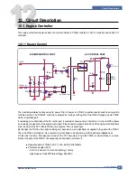
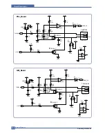
If the fuser (P3.7) port becomes high, the Q6 is activated. A heat lamp starts operating by the activity.
As the temperature of the heat lamp is increased, the resistance value of the thermister is decreased.
Therefore, the electric potential of the circled A becomes low.
On/Off operation of the Q6 is only controlled by the fuser (P3.7) port because 5(+) of the
U11(Comparator) is always higher than 6 (-) within the normal control temperature rage.
Functions of the Malfunction Protection:
If the fuser port (P3.7) is turned on regardless of controlling due to system malfunction, the tempera-
ture of the heat roller goes abnormally high. At this time, the resistance value of the thermister becomes
low.
When the resistance value of the thermister becomes low, the electric potential of the circled A gets low,
and when the temperature goes over the certain temperature, the comparator (U11) gets a low output.
As a result, even though the fuser port is abnormally activated, it is disable to be over the regular tem-
perature. For maintaining a regular temperature, a protect circuit consists in it (This protection is set up
to start operating at the rage between 205°~210°)
12.1.2 PWM Controller
Function Description
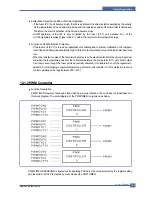
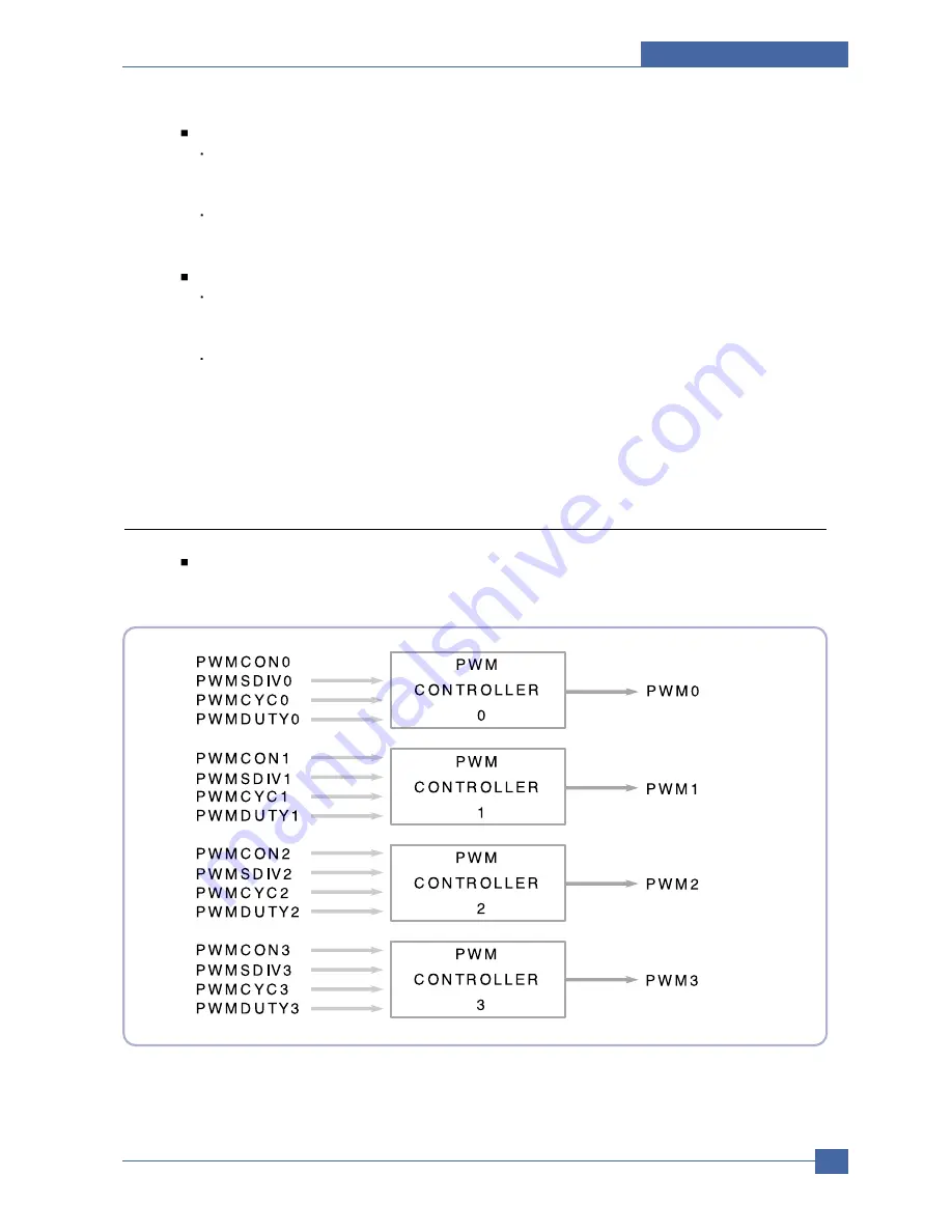
PWM TIMER consists of each sub block which has various functions. The sub block is divided based on
this block diagram. The entire diagram of the PWMTIMER is organized as below.
PWM TIMER OPERATION is figured out if calculating PHCLK by the value selected by the register setting
and the divider. PHCLK is created by count block at the PWM TIMER
Summary of Contents for ML-2510 series
Page 29: ...System Overview Samsung Electronics Service Manual 3 15 3 2 3 5 SPGPv3 Internal Block Diagram ...
Page 103: ...Exploded Views Parts List 7 2 Frame Assembly 0 15 13 12 4 14 3 2 16 5 7 6 16 1 9 11 10 8 ...
Page 106: ...Exploded Views Parts List 7 5 RX_Drive 0 6 3 4 9 10 8 7 11 2 5 ...
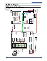
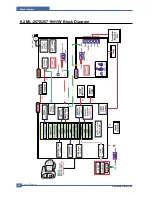
Page 115: ...Service Manual Block diagram 8 2 Samsung Electronics 8 2 ML 2570 2571N H W Block Diagram ...
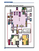
Page 117: ...Service Manual Connection Diagram 9 2 9 2 ML 2570 2571N Connection Diagram ...


