background image

English 

_43


INST

ALLA

TION & CONNECTION

CONNECTING WITH OTHER DEVICE

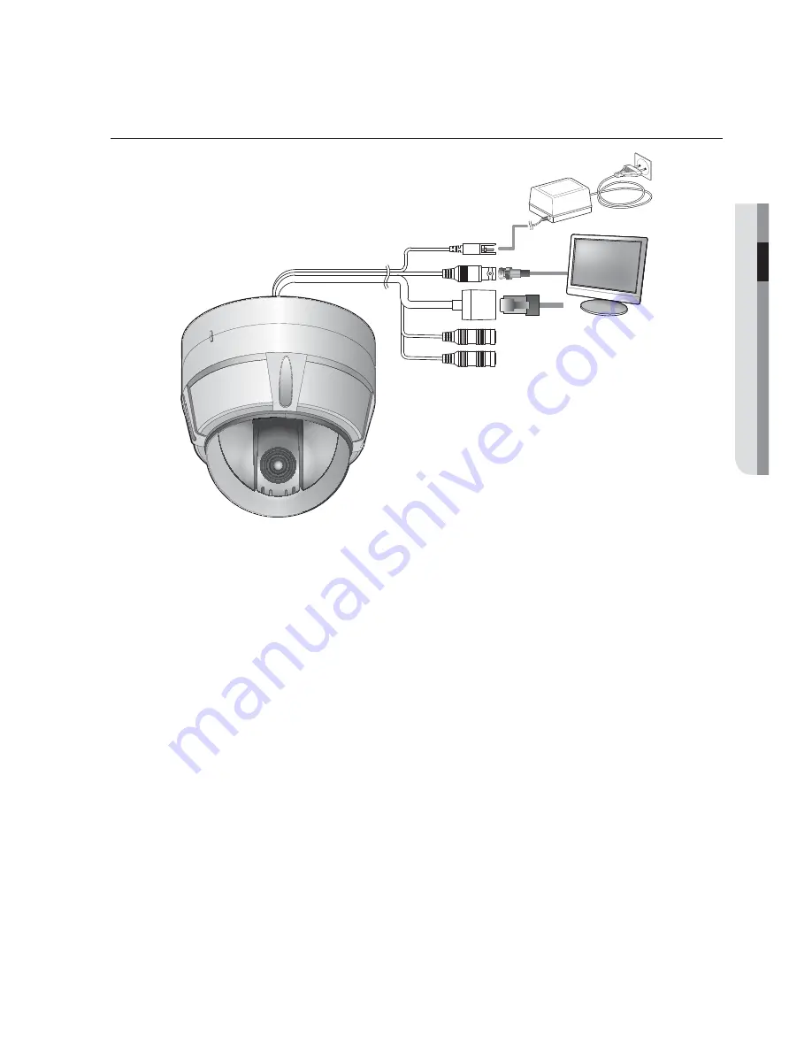
Connecting to the monitor 

Connect the video out port of the camera to the video input port of the monitor.


M


In the initial installation of the camera, you can connect the camera to the monitor for checking 
the connection status.


Connect the monitor test cable to the output port of the monitor.

Ethernet Connection

Connect the Ethernet cable to the local network or to the Internet.

Power Supply

Use the screwdriver to connect each line (+, –) of the power cable to the corresponding 
power port of the camera.


J


You can also use a router featuring PoE (Power over Ethernet) to supply power to the camera.


If using PoE, the heater will not operate at all. (SNP-3120V/VH)
Use an adaptor if the installation site requires heater operations. Adaptor is sold separately. 
For the power specifications, refer to the “

Appendix

”. (page 108)

Monitor

Power

Ethernet

Summary of Contents for iPOLiS 3120V

Page 1: ...NETWORK CAMERA User Manual SNP 3120 3120V 3120VH ...

Page 2: ...cument and the subsequent results shall be entirely on the user s own responsibility Samsung Techwin reserves the right to change the contents of this document without prior notice Warranty If the product does not operate properly in normal conditions please let us know Samsung Techwin will resolve the problem for free of charge The warranty period is 3 years However the followings are excluded If...

Page 3: ...fit into your outlet consult an electrician for replacement of the obsolete outlet 10 Protect the power cord from being walked on or pinched particularly at plugs conve nience receptacles and the point where they exit from the apparatus 11 Only use attachments accessories specified by the manufacturer 12 Use only with the cart stand tripod bracket or table specified by the manufacturer or sold wit...

Page 4: ...UCE THE RISK OF ELECTRIC SHOCK DO NOT REMOVE COVER OR BACK NO USER SERVICEABLE PARTS INSIDE REFER SERVICING TO QUALIFIED SERVICE PERSONNEL EXPLANATION OF GRAPHICAL SYMBOLS The lightning flash with arrowhead symbol within an equilateral triangle is intended to alert the user to the presence of dangerous voltage within the product s enclosure that may be of sufficient magnitude to constitute a risk ...

Page 5: ... risk of lightening may cause damage or malfunction to the product Please use the input power with just one camera and other devices must not be connected Do not expose the product to the direct airflow from an air conditioner Otherwise it may cause moisture condensation inside the Clear Dome due to temperature difference between internal and external of the dome camera If you install this product...

Page 6: ...aused by not following the instruction Please read this manual for the safety before using of goods and keep it in the safe place Do not place this apparatus on an uneven surface Do not install on a surface where it is exposed to direct sunlight near heating equipment or heavy cold area Do not place this apparatus near conductive material Do not attempt to service this apparatus yourself Do not pl...

Page 7: ... case the user will be required to correct the interference at his own expense Correct Disposal of This Product Waste Electrical Electronic Equipment Applicable in the European Union and other European countries with separate collection systems This marking on the product accessories or literature indicates that the product and its electronic accessories e g charger headset USB cable should not be...

Page 8: ...emoving an SD Memory Card 42 Memory Card Information Not Included 43 Connecting with other Device NETWORK CONNECTION AND SETUP 46 46 Connecting the Camera Directly to Local Area Networking 47 Connecting the Camera Directly to a DHCP Based DSL Cable Modem 48 Connecting the Camera Directly to a PPPoE Modem 49 Connecting the Camera to an IP Router with the PPPoE Cable Modem 50 Buttons used in IP Inst...

Page 9: ...ideo Setup 88 Network Setup 93 Event Setup 99 System Setup WEB VIEWER 58 58 Connecting to the Camera 59 Login 60 Installing Silverlight Runtime 62 Using the Live Screen 65 Playback 66 Playing the backup recordings APPENDIX 104 104 Specification 109 Product Overview 111 Troubleshooting 113 Open Source Announcement 115 GPL LGPL Software License ...

Page 10: ... event signal will be sent to the Alarm Out port Intelligent Video Analysis Analyzes the event video according to the user specified rules to recognize the event ONVIF Spec 1 02 Compliance This product supports ONVIF Core Spec 1 02 For more information refer to www onvif org RECOMENDED PC SPECIFICATIONS CPU Intel R Core TM 2 2 00 GHz or higher Operating System Windows XP VISTA 7 Mac OS Resolution ...

Page 11: ...e Appearance Item Name Quantity Description Model Name User Manual Installer S W DVD CMS S W DVD 2 SNP 3120 3120V 3120VH Quick Guide 1 7Pin Terminal Block 1 For communications 8Pin Terminal Block 1 For alarm I O Cable for the testing monitor 1 Used to test the camera connection to a portable display device Audio cable 1 ...

Page 12: ...SY Tapping Screw 4 Used for installation on the wall or ceiling Mount Bracket 1 SNP 3120 L Wrench 1 Used to remove fix the dome cover SNP 3120V 3120VH M The Test Monitor Cable is connected to a portable displayer and used for testing the camera If you intend to use it for an actual monitoring camera use the BNC cable instead ...

Page 13: ... camera ID or communication protocol Screw Hole Used to fix the camera to the wall or ceiling Reset Button Resets the camera settings to the default Press and hold it for about 5 seconds to turn off the system indicator and restart the system J If you reset the camera the network settings will be adjusted so that DHCP can be enabled If there is no DHCP server in the network you must run the IP Ins...

Page 14: ...d with frost Video RS 485 Power Used to connect monitor RS 485 device or power ID setup switch Used to setup the camera ID or communication protocol Reset Button Resets the camera settings to the default Press and hold it for about 5 seconds to turn off the system indicator and restart the system J If you reset the camera the network settings will be adjusted so that DHCP can be enabled If there i...

Page 15: ...o connect monitor RS 485 device or power ID setup switch Used to setup the camera ID or communication protocol Reset Button Resets the camera settings to the default Press and hold it for about 5 seconds to turn off the system indicator and restart the system J If you reset the camera the network settings will be adjusted so that DHCP can be enabled If there is no DHCP server in the network you mu...

Page 16: ...nal connection is not required Controller Auxiliary Signal Connection No Name Usage 1 2 COM Alarm Output 2 Common 2 2 NO Alarm Output 2 Normal Open 3 1 COM Alarm Output 1 Common 4 1 NO Alarm Output 1 Normal Open 5 1 NC Alarm Output 1 Normal Open 6 GND Ground 7 IN1 Alarm Input Sensor Terminal 1 8 IN2 Alarm Input Sensor Terminal 2 ALARM ID PROTOCOL VIDEO 485 POWER ...

Page 17: ...Power supply adaptor AC has no polarities J The maximum power capacity of the built in relay is 30V DC 2A 125V AC 0 5A and 250V AC 0 25A Connecting the power connector and GND incorrectly to the NC NO and COM ports may cause a short circuit and fi re damaging the camera When connecting the camera to an external over rated product use a separate relay device to ensure proper operation To prevent po...

Page 18: ...o the installation environment 1 Detach the camera frame from the install base and place the bottom of the frame toward you as shown in the picture below 2 Set the switches according to your installation environment For more detailed setup information please refer to the chart on the next page 3 The camera may malfunction if the switches are not fully turned On Off please double check the switches...

Page 19: ...s Protocol Settings Select a communication protocol for the camera No Protocol SW2 1 SW2 2 SW2 3 SW2 4 1 AUTO DETECT OFF OFF OFF OFF 2 Samsung T OFF OFF OFF ON 3 Pelco D OFF OFF ON OFF 4 Pelco P OFF OFF ON ON 5 Samsung E OFF ON OFF OFF 6 Panasonic OFF ON OFF ON 7 Vicon OFF ON ON OFF 8 Honeywell OFF ON ON ON 9 AD ON OFF OFF OFF 10 GE ON OFF OFF ON 11 BOSCH ON OFF ON OFF 12 Reserved ON OFF ON ON 13 ...

Page 20: ... for the camera and controller Response or No Response Function ON OFF SW2 7 Response Mode Switch Response No Response Termination Settings To prevent the attenuation of communication signals between the camera and controller the items at the end of line must be set up with the termination settings Camera Input Position SW2 8 Termination of Longest Path ON On the Path OFF This model is provided wi...

Page 21: ...Protocol VICON Protocol GE Protocol Entering Camera OSD 3 Auxilary ON IRIS OPEN IRIS OPEN Exiting Camera OSD 3 Auxilary OFF IRIS CLOSE IRIS CLOSE ENTER IRIS OPEN IRIS OPEN IRIS OPEN ESC IRIS CLOSE IRIS CLOSE IRIS CLOSE For more information about the protocols refer to our official website Camera ID DIP Switch Settings SW1 To set up camera IDs refer to the Camera ID Chart next ON ON OFF SW1 ...

Page 22: ... OFF ON OFF OFF OFF 17 ON OFF OFF OFF ON OFF OFF OFF 18 OFF ON OFF OFF ON OFF OFF OFF 19 ON ON OFF OFF ON OFF OFF OFF 20 OFF OFF ON OFF ON OFF OFF OFF 21 ON OFF ON OFF ON OFF OFF OFF 22 OFF ON ON OFF ON OFF OFF OFF 23 ON ON ON OFF ON OFF OFF OFF 24 OFF OFF OFF ON ON OFF OFF OFF 25 ON OFF OFF ON ON OFF OFF OFF 26 OFF ON OFF ON ON OFF OFF OFF 27 ON ON OFF ON ON OFF OFF OFF 28 OFF OFF ON ON ON OFF OF...

Page 23: ...59 ON ON OFF ON ON ON OFF OFF 60 OFF OFF ON ON ON ON OFF OFF 61 ON OFF ON ON ON ON OFF OFF 62 OFF ON ON ON ON ON OFF OFF 63 ON ON ON ON ON ON OFF OFF 64 OFF OFF OFF OFF OFF OFF ON OFF 65 ON OFF OFF OFF OFF OFF ON OFF 66 OFF ON OFF OFF OFF OFF ON OFF 67 ON ON OFF OFF OFF OFF ON OFF 68 OFF OFF ON OFF OFF OFF ON OFF 69 ON OFF ON OFF OFF OFF ON OFF 70 OFF ON ON OFF OFF OFF ON OFF 71 ON ON ON OFF OFF O...

Page 24: ...F ON ON OFF 102 OFF ON ON OFF OFF ON ON OFF 103 ON ON ON OFF OFF ON ON OFF 104 OFF OFF OFF ON OFF ON ON OFF 105 ON OFF OFF ON OFF ON ON OFF 106 OFF ON OFF ON OFF ON ON OFF 107 ON ON OFF ON OFF ON ON OFF 108 OFF OFF ON ON OFF ON ON OFF 109 ON OFF ON ON OFF ON ON OFF 110 OFF ON ON ON OFF ON ON OFF 111 ON ON ON ON OFF ON ON OFF 112 OFF OFF OFF OFF ON ON ON OFF 113 ON OFF OFF OFF ON ON ON OFF 114 OFF ...

Page 25: ... OFF ON 145 ON OFF OFF OFF ON OFF OFF ON 146 OFF ON OFF OFF ON OFF OFF ON 147 ON ON OFF OFF ON OFF OFF ON 148 OFF OFF ON OFF ON OFF OFF ON 149 ON OFF ON OFF ON OFF OFF ON 150 OFF ON ON OFF ON OFF OFF ON 151 ON ON ON OFF ON OFF OFF ON 152 OFF OFF OFF ON ON OFF OFF ON 153 ON OFF OFF ON ON OFF OFF ON 154 OFF ON OFF ON ON OFF OFF ON 155 ON ON OFF ON ON OFF OFF ON 156 OFF OFF ON ON ON OFF OFF ON 157 ON...

Page 26: ...OFF ON 188 OFF OFF ON ON ON ON OFF ON 189 ON OFF ON ON ON ON OFF ON 190 OFF ON ON ON ON ON OFF ON 191 ON ON ON ON ON ON OFF ON 192 OFF OFF OFF OFF OFF OFF ON ON 193 ON OFF OFF OFF OFF OFF ON ON 194 OFF ON OFF OFF OFF OFF ON ON 195 ON ON OFF OFF OFF OFF ON ON 196 OFF OFF ON OFF OFF OFF ON ON 197 ON OFF ON OFF OFF OFF ON ON 198 OFF ON ON OFF OFF OFF ON ON 199 ON ON ON OFF OFF OFF ON ON 200 OFF OFF O...

Page 27: ...230 OFF ON ON OFF OFF ON ON ON 231 ON ON ON OFF OFF ON ON ON 232 OFF OFF OFF ON OFF ON ON ON 233 ON OFF OFF ON OFF ON ON ON 234 OFF ON OFF ON OFF ON ON ON 235 ON ON OFF ON OFF ON ON ON 236 OFF OFF ON ON OFF ON ON ON 237 ON OFF ON ON OFF ON ON ON 238 OFF ON ON ON OFF ON ON ON 239 ON ON ON ON OFF ON ON ON 240 OFF OFF OFF OFF ON ON ON ON 241 ON OFF OFF OFF ON ON ON ON 242 OFF ON OFF OFF ON ON ON ON 2...

Page 28: ... connect the camera to a power outlet until the installation is complete Supplying power in the middle of the installation may cause fire or damage the product 3 Connect each camera cable to the proper terminals on the bottom of the camera For more detailed instructions please refer to Page 16 Camera Wiring Interface Board 4 DIP switches for communication and ID setup are located on the bottom of ...

Page 29: ... the marking shown as A in the diagram on the left of the FRONT side of the Mount Bracket 6 After inserting the camera into the Mount Brack et turn the camera module clockwise about 25 7 Match the screw holes in the camera and mount bracket and then fasten with the screw Screw Hole Mount Bracket A ...

Page 30: ...n drill a hole according to the 143 mm diameter hole marked on the template Drop down the camera cables through the hole Drill another small hole for a screw to secure the camera 2 Rotate the dome cover counterclockwise to detach it from the camera 3 Remove the 3 screws and then detach the mount housing from the camera ...

Page 31: ...ure the DIP switches on the bottom of the camera for communication and ID Refer to pages 19 21 5 Install Camera Fit the camera to the hole on the ceiling and then secure the camera using 3 Product enclosed Fixture Screws M4x20 6 Assemble Dome Cover Insert the grooves on the dome cover into ones on the camera and then turn clockwise to fasten Ceiling Screw Screw Ceiling ...

Page 32: ..._ installation connection INSTALLING WITH ACCESSORIES SOLD SEPARATELY 1 Turn the Dome Cover counter clockwise and separate from the camera 2 Remove 3 screws and separate the Mount Housing from the camera Dome Cover Mount Housing ...

Page 33: ...he mount housing 4 Connect wires to the Terminal Block and attach it to the bot tom side of the camera Refer to the Camera Wiring Interface Board at page 16 Set the communication protocol and ID DIP switches on the bottom of the camera unit Refer to pages 19 21 5 Fix the camera to the Mount Housing by using 3 screws removed in the step 2 6 Attach the Dome Cover and turn it clockwise to fix Hanging...

Page 34: ...kwise 2 Drill holes 5 mm in diameter and at least 35 mm in depth for each for the screws x4 to be inserted in the bottom of the surface mount and insert the provided plastic anchor HUD5 to the end Insert the cables into the cable hole and fix the SCREW TAPPING TH M4xL30 to the plastic anchor that was inserted in the hole for fixing the surface mount x4 Surface Body Screw Surface Mount ...

Page 35: ...cables inside the surface mount so that they should not be entangled or stuck in and align the guide rib of the camera with that of the surface mount Use the L shaped wrench to tighten the screws x4 so that the camera is secured to the mount To ensure waterproofness take caution lest that the outer gasket should get loose or be stuck in Safety wire Screw Main frame Gasket Guide Rib of Main frame G...

Page 36: ...1 Follow step 1 in Ceiling Mount above and remove the surface mount 2 Insert the cables into the cable hole on the surface mount and fix them to SBP 300HM HANGING MOUNT using SCREW MACHINE BH M4xL10 x4 3 Repeat step 3 through step 4 in Ceiling Mount above to complete the installation ...

Page 37: ...ich will help removing the housing 2 Fix the housing to the NP 1 5 tapped pipe wall mount SBP 300WM or ceiling mount SBP 300CM by turning it clockwise For waterproofness and lock between the two component parts use the Teflon tape to wrap them around Pipe or Mount Pipe or Mount Housing Housing NP 1 5 TAP Housing Main frame Screw Screw ...

Page 38: ...ra Wiring Interface Board section in this manual 4 Arrange the cables inside the housing lest they be damaged or stuck in and use the L shaped wrench to tighten 4 screws to the housing To ensure waterproofness this step needs your special care Otherwise the gasket on the outer side of the product may be loose or just stuck in Gasket Housing Main frame Screw Safety wire Safety wire ...

Page 39: ...appropriate optional accessories available 1 When installing the camera on a wall SNP 3120 SNP 3120V Wall mount SBP 300WM Hanging mount SBP 300HM SNP 3120VH Wall mount SBP 300WM 2 When installing the camera on a ceiling SNP 3120 SNP 3120V Ceiling mount SBP 300CM Hanging mount SBP 300HM SNP 3120VH Celling mount SBP 300CM ...

Page 40: ...installing the Wall Mount SBP 300WM on a pole bigger than 80mm in diameter Pole Mount SBP 300PM 4 When installing the Wall Mount SBP 300WM on a cornered wall Corner Mount SBP 300KM 5 When installing SNP 3120VH on a rooftop of a building Parapet Mount SBP 300LM ...

Page 41: ...g an SD Memory Card Gently press down on the exposed end of the memory card as shown in the diagram to eject the memory card from the slot J Pressing too hard on the SD memory card can cause the card to shoot out uncontrollably from the slot when released To remove the SD memory card set Record to Off from SD record and press Apply page 94 If you have saved data in the SD memory card removing the ...

Page 42: ...nding on the model and make of the memory card For your camera we recommend you use a memory card from the following manufacturers SDHC SD Memory Card Sandisk Transcend Kingston Playback performance can be affected depending on the speed of memory card so use the high speed memory card Memory Card Use SD and SDHC memory cards feature a switch that disables writing data on to the media Having this ...

Page 43: ...the monitor Ethernet Connection Connect the Ethernet cable to the local network or to the Internet Power Supply Use the screwdriver to connect each line of the power cable to the corresponding power port of the camera J You can also use a router featuring PoE Power over Ethernet to supply power to the camera If using PoE the heater will not operate at all SNP 3120V VH Use an adaptor if the install...

Page 44: ...one is connected to 2 Connect the AUDIO OUT port of the camera with the LINE IN port of the speaker 3 Check the specifications for audio input Audio Codec G 711 PCM μ law 64kbps 8kHz sampling Full duplex Audio Audio in Used for mono signal line input Max 2 4 Vpp Audio out Used for mono signal line output Max 2 4 Vpp Line out impedance 600 PC Speaker Microphone Amp Amp Microphone Network Speaker Mi...

Page 45: ... the Alarm I O signal to the corresponding port of the rear port box M For further details on each terminal refer to Camera Wiring Interface Board page 16 1 AUX COM AUX NO ALM1 COM ALM1 NO ALM1 NC ALM IN1 ALM IN2 GND 2 3 4 5 6 7 8 1 2 COM 5 1 NC 2 2 NO 6 GND 3 1 COM 7 IN1 4 1 NO 8 IN2 1 2 3 4 5 6 7 8 ...

Page 46: ...ble to connect to the camera installed in the intranet if the port forwarding is not properly set or a firewall is set In this case to resolve the problem contact your network administrator By factory default the IP address will be assigned from the DHCP server automatically If there is no DHCP server available the IP address will be set to 192 168 1 100 To change the IP address use the IP Install...

Page 47: ...rnet browser to connect to the camera 4 Move to Setup page 5 Move to Network DDNS and configure the DDNS settings 6 Move to Network Interface and set the network type to DHCP 7 Connect the camera which was removed from your PC directly to the modem 8 Restart the camera M For registering the DDNS settings refer to Registering with DDNS page 90 For configuring the DDNS settings refer to DDNS page 89...

Page 48: ...Internet browser to connect to the camera 4 Move to Setup page 5 Move to Network DDNS and configure the DDNS settings 6 Move to Network Interface and set the network type to PPPoE 7 Connect the camera which was removed from your PC directly to the modem 8 Restart the camera M For registering the DDNS settings refer to Registering with DDNS page 90 For configuring the DDNS settings refer to DDNS pa...

Page 49: ... below if you select Use the following IP address ex1 If the address LAN IP of the IP router is 192 168 1 1 IP address 192 168 1 100 Subnet Mask 255 255 255 0 Default Gateway 192 168 1 1 ex2 If the address LAN IP of the IP router is 192 168 0 1 IP address 192 168 0 100 Subnet Mask 255 255 255 0 Default Gateway 192 168 0 1 ex3 If the address LAN IP of the IP router is 192 168 xxx 1 IP address 192 1...

Page 50: ...ction status c MAC Ethernet Address Ethernet address for the connected camera Click the column to sort the list by Ethernet address However search will be stopped if clicked during the search IP Address IP address Click the column to sort the list by IP address However search will be stopped if clicked during the search The factory default is 192 168 1 100 Protocol Network setting for the camera T...

Page 51: ...nstaller program M For the IP installer use only the installer version provided in the installation DVD or use the latest one if available You can download the latest version from the product website STATIC IP SETUP Manual Network Setup Run IP Installer_vX XX exe to display the camera search list At the initial startup both Auto Set and Manual Set will be grayed out M For cameras found with the IP...

Page 52: ...e Local IP Address of the IP router will be the Gateway of the camera M The settings may differ depending on the connected IP router model For more information refer to the user manual of the applicable router Refer to the Port Range Forward Port Mapping Setup section of the IP Router s documentation Page 55 If not using an IP router For setting IP Address Subnet Mask and Gateway contact your netw...

Page 53: ...0 192 168 1 1 192 168 1 101 255 255 255 0 192 168 1 1 Port related settings HTTP Port VNP Port 8080 4520 8081 4521 M If the HTTP Port is set other than 80 you must provide the Port number in the address bar of the Internet browser before you can access the camera ex http IP address HTTP Port http 192 168 1 100 8080 Auto Network Setup Run IP Installer_vX XX exe to display the camera search list At ...

Page 54: ... Click OK Auto network setup will be completed DYNAMIC IP SETUP Dynamic IP Environment Setup Example of the Dynamic IP environment If an IP router with cameras connected is assigned an IP address by the DHCP server If connecting the camera directly to modem using the DHCP protocols If IPs are assigned by the internal DHCP server via the LAN Checking the Dynamic IP 1 Run the IP Installer on the use...

Page 55: ...For setting the port range forward for a third party IP router refer to the user guide of that IP router 2 Select TCP and UDP Port for each connected camera to the IP router Each port number for the IP router should match that specified in Network Port from the cam era s Setup menu 3 When done click Save Settings Your settings will be saved M Above sample instructions are based on the CISCO s IP R...

Page 56: ...t a rule of Port Forwarding on the IP router device through its configura tion web page You cannot change the Silverlight policy server port of a camera You can change the ports of the camera except the policy server port through its configuration web pages User Internet Ù IP router Start End Protocol IP Address 943 943 TCP 192 168 1 100 3000 3000 TCP UDP 192 168 1 100 3001 3001 TCP UDP 192 168 1 ...

Page 57: ...t browser CONNECTING TO THE CAMERA FROM A REMOTE PC VIA THE INTERNET Since using the IP Installer on a remote computer that is not in the IP Router s network cluster is not allowed users can access cameras within an IP Router s network by using the camera s DDNS URL 1 Before you can access a camera in the IP router network you should have set the port range forward for the IP router 2 From the rem...

Page 58: ...0000 ffff 1111 http 2001 230 abcd ffff 0000 0000 ffff 1111 If the HTTP port is other than 80 1 Launch the Internet browser 2 Type the IP address and HTTP port number of the camera in the address bar ex IP address 192 168 1 100 HTTP Port number 8080 http 192 168 1 100 8080 the Login dialog should appear Using URL 1 Launch the Internet browser 2 Type the DDNS URL of the camera in the address bar ex ...

Page 59: ...the User Name input box 2 Enter 4321 in the Password input box If the password is changed enter the changed password instead 3 Click OK If you have logged in successfully you will the Live Viewer screen M For security purposes ensure that you change the password in System User The administrator ID admin is fixed and can not be changed The default password can be exposed to a hacking thread so it i...

Page 60: ...e or has just installed an old runtime version you will be redirected to the Silverlight Runtime installation page automatically when accessing the web viewer 1 Click Click Here 2 When the file download dialog pops up click Run 3 When the download is completed click Run 4 The Silverlight Runtime installation page will be displayed Install now to pro ceed with the installation ...

Page 61: ...screen J For normal installation set the Block Popup setting as follows Internet Explorer Tools Block Popup Always allow popups from the current site A However MAC OS X users who are not connected to the Internet can use the provided installation DVD to install Silverlight Runtime Run the executable Silverlight_xxx dmg in the DVD You will be guided through installation of the software ...

Page 62: ...the Setup screen Viewer Screen Displays the Live video on the screen Alarm Output Activate the Alarm Out port Audio Display the audio Listen and Talk toggle button on the screen Hide the alarm indicator Hides the alarm indicator near the border of the viewer screen Camera Menu Used to retrieve and customize the Camera Setup menu For selecting and saving each menu item refer to Using the Camera Men...

Page 63: ...etup menu M For IE 6 0 users press the Browse button next to the Video profile dialog and select a profile type again if the selected profile is not played M If the Invalid codec message is displayed select a profile type from the profile list again M If the temperature drops below the operational range video signal may not be produced In such cases please wait for the video To capture the snapsho...

Page 64: ...lick the button to start stop talking This button operates as a toggle button The Silverlight permission dialog appears when you click the microphone button To fit the full screen 1 Click the Full Screen button The corresponding button will be displayed in the Viewer 2 Click the button This will fit the Viewer to the full screen 3 To exit the full screen mode press Esc on the keyboard To control t...

Page 65: ...od your search will be limited up to the date when the 500th event is recorded For instance if the search period is between 10th and 15th day of the month and more than 800 events were recorded 10th through 11th your search will be limited up to 11th day with a total of 800 events and events after then from 12th will not be found 5 Select a data item to play in the search list 6 Click the Play but...

Page 66: ...8 as the default web browser select Tools Internet Options Security and uncheck Use protected mode PLAYING THE BACKUP RECORDINGS You can play backup recordings by using the SlimPlayer To download SlimPlayer 1 Click SlimPlayer You will see a download dialog where you can specify the download path 2 Specify the path with a proper file name and click Save 3 Unzip the downloaded file and run the execu...

Page 67: ... menu item click Enter 6 To move to previous menu or exit the menu setup click Cancel button This arrow appears next to a menu that contains sub items J If IV analysis function is enabled camera s OSD menu operation can be set as an event CAMERA SETTING You can set up the general functions of camera module Starting the Menu 1 Click Camera Menu button 2 When main menu shows up on screen move to des...

Page 68: ...ground illumination is low While Slow Shutter is in operation If the zoom level is set too high When background illumination is too high If a long distance object and a close distance object appear together within a monitoring area If there is no contrast e g Ceiling or a wall If the camera is facing a thin horizontal line Auto Focus focuses on an object in the center of the screen objects around ...

Page 69: ...is setting may require an readjustment if the lighting conditions changes MANUAL Enables customization of the Red and Blue gains M White Balance may not work properly under the following conditions When the color temperature of the environment surrounding the subject is out of the control range When the ambient illumination of the subject is dim If the camera is directed towards a fluorescent ligh...

Page 70: ...with camera frame rates MANUAL Enables manual adjustment of the shutter speed Sens Up AUTO Automatically detects light levels and maintains a clear picture at night or under low light conditions Sens Up Limit Adjusts to the maximum powered zoom per frame M While the Internal Sync mode is in effect setting the shutter to and facing the camera directly to a bright light source may cause poor camera ...

Page 71: ...the contrast in the light and dark areas becomes Level Adjusts the screen brightness in WDR mode M WDR is disabled when the VPS mode is turned on WDR is disabled if the Iris is in Manual mode During WDR operation noise discoloration spots and whitish symptoms may occur depending on lighting conditions If they occur stop using WDR Camera Setting Camera Setting Zoom Focus Zoom Focus White Balance AT...

Page 72: ...conditions Main Menu Ö Camera Setting Ö AGC The OFF LOW MEDIUM HIGH and MANUAL modes are available M If you select the AUTO for Day Night you cannot use the AGC menu Camera Setting Camera Setting Zoom Focus Zoom Focus White Balance ATW IN White Balance ATW IN Exposure Exposure Back Light Back Light BLC BLC AGC AGC DNR MEDIUM DNR MEDIUM XDR OFF XDR OFF Day Night Day Night Others Others BLC BLC Up U...

Page 73: ...ots of an image while retaining the same light level for brighter spots to even out the overall brightness of the image with high contrast between bright and dark spots Main Menu Ö Camera Setting Ö XDR The OFF LOW MEDIUM and HIGH modes are available Camera Setting Camera Setting Zoom Focus Zoom Focus White Balance ATW IN White Balance ATW IN Exposure Exposure Back Light OFF Back Light OFF AGC AGC ...

Page 74: ... W mode and connected to equipment that requires external sync through burst signals set the Burst On Off option to On Dwell Time The duration of both the lighting conditions can be customized to let the cam era delay the switching between the daytime and night time settings M Using B W mode under sunlight or a halogen lamp may decrease the focusing performance Camera Setting Camera Setting Zoom F...

Page 75: ...d of view has very low or no contrast e g The sky or a white wall VPS is disabled when the Freeze is turned on Image Hold Main Menu Ö P T Setting Ö Image Hold When the camera is moving between presets locations this function freezes the cameras image until the camera reached the next location This is useful to help the screen observer keep sharp eyes and to monitor multiple locations within a netw...

Page 76: ...peed regardless of the angle of the controller handle Max Speed Level Adjusts the maximum speed of Pan and Tilt while performing the Preset and Sequencing actions Main Menu Ö P T Setting Ö Max Speed Level 1 7 Pan and Tilt operations can be set up to 650 sec P T Setting P T Setting Image Hold OFF Image Hold OFF Jog Speed Jog Speed MANUAL MANUAL Max Speed Level 5 Max Speed Level 5 P T Setting P T Se...

Page 77: ...e and Preset Name the screen displays the Left keypad Names can be up to 12 characters and can be entered via the joystick and the Enter key Once a name is entered use the joystick and the Enter key to perform the Set command and save the name Main Menu Main Menu Camera Setting Camera Setting P T Setting P T Setting OSD Setting OSD Setting Initialize Initialize OSD Setting OSD Setting Camera ID ON...

Page 78: ...ustomize the camera clock you can schedule sequence actions to perform automatically Display Shows or hides the clock from the screen Date Format Changes the display format of the camera date DD MM YYYY or MM DD YYYY OSD Setting OSD Setting Camera ID ON Camera ID ON Camera Name Camera Name Seq Status ON Seq Status ON PTZ Position ON PTZ Position ON Language ENGLISH Language ENGLISH Others Others O...

Page 79: ...edly rotated in all four directions for a long time to moni tor a specific location The default setting is Off OFF 1 7 Days Selecting Off disables Auto Refresh and selecting 1 7 Days automatically executes it after 1 7 days has passed M Auto Refresh takes approximately 10 seconds to finish If Auto Refresh activates in the middle of a sequence action the camera pauses the sequence action and perfor...

Page 80: ... differ depending on the selected codec type Default profile This is the default video profile Fixed framerate profile Fix the frame rate of the selected profile regardless of the settings of other profiles E mail FTP profile Video profile to be transferred to the specified email or FTP site Only the MJPEG codec can be set as the E mail FTP profile Record profile This is the profile that is applie...

Page 81: ... transfer method to Framerate or Compression GOP size Select a GOP size between 1 and 15 Profile You can select the H 264 profiling method Entropy coding Reduce the possible compression loss due to encoding Multicast VNP Specify the use of the VNP protocol IPv4 Enter an IPv4 address with which you can connect to the IPv4 network Port Specify the video communication port TTL Set the TTL for the VNP...

Page 82: ...yed in mosaic pixels 4 Click an area on the image and select 4 corner points to specify a desired zone A popup appears where you enter a name for the zone and click Apply Do not drag an area to specify a privacy zone it does not work 5 To delete the selected area click Delete 6 When done click Apply You can specify up to 12 zones Audio setup You can configure the I O settings of the audio source f...

Page 83: ...bigger the number is the faster the moving speed becomes 4 Set the zoom and focus control buttons Zoom In Zooms in the screen Zoom Out Zooms out the screen Adjust Focus Adjusts the focus in the screen Zoom Speed Control The bigger the number is the faster the zoom speed becomes 5 Set the preset To add a preset 1 Select the preset number to add 2 Set the name for the preset 3 Press the button To de...

Page 84: ...Iris Level SHUTTER Mode Off Manual A FLK Shutter Speed Sens up Mode Off ON Sens up Limit BackLight Select one from Off WDR WDR Level WDR Limit User Day Night AGC Select one from Color Black and White Auto Others Set DNR Off Low Middle High XDR Off Low Middle High as appropriate 4 When done click Apply To configure the swing settings Swing is a monitoring function that moves between two preset poin...

Page 85: ...tch to the group setting screen 2 Select a group setting mode Group No Select a group number Preset No Select a preset number Speed Specify the speed of movement Dwell time Specify the duration for which an operation is kept at the preset position 3 Press the button Your settings will be entered in the right list 4 Press the button Selected group data will be deleted To configure the tour settings...

Page 86: ...setup to Trace Auto Run The menu screen will switch to the PTZ tracking and Auto operation menu screen 2 Select a tracking number You can save the trace in memory within 120 seconds The saving time may differ depending on the difficulty of the PTZ operation The operation will be saved in memory with the memory status displayed When the memory is full and the EEPROM 000 message appears tracking wil...

Page 87: ...tically executes the operation in Tour mode Trace Automatically executes the operation in Trace mode Auto pan Automatically executes the 360 rotation in the pan direction Auto Pan requires two options that need your settings tilting angle and pan speed 3 Press the button PTZ limit You can specify restrictions on the pan or tilt function 1 From the Setup menu select the Audio Video tab 2 Click PTZ ...

Page 88: ...ld specify the IP Subnet Mask Gateway DNS 1 2 manually MAC address Shows the MAC address IP address Displays the current IP address Subnet mask Displays the Subnet mask for the set IP Gateway Displays the Gateway for the set IP DNS1 DNS2 Displays the DNS Domain Name Service server address IPv6 use Specify the use of IPv6 IPv6 address Obtains the IPv6 address to access the IPv6 network 4 When done ...

Page 89: ... of the Viewer is between 4502 and 4534 If the VNP port is with this effective range the Viewer port should be specified the same as the VNP port 4 When done click Apply DDNS DDNS is an abbreviation of Dynamic Domain Name Service that converts the IP address of a camera into a general Host Name so that the user can easily remember it 1 From the Setup menu select the Network tab 2 Click DDNS 3 Sele...

Page 90: ...that is registered with Dyndns 5 When done click Apply Registering with DDNS To register your product with the Samsung DDNS 1 Visit the iPOLiS web site www samsungipolis com and sign in with a registered account 2 From the top menu bar select DDNS SERVICE MY DDNS 3 Click PRODUCT REGISTRATION 4 Enter the product domain You must perform the duplicate check for the domain that you entered ...

Page 91: ...S setup page set DDNS to Samsung DDNS 2 Provide the Host name that you reg istered product domain with the DDNS site 3 Click Apply When the connection is successfully made you will see the message of Success on the screen Configuring public DDNS in Camera Settings 1 Open the DDNS settings page and select Public DDNS for DDNS 2 Enter the corresponding site s host name user name and password 3 Click...

Page 92: ...ecure connection system or install the public certificate for this purpose 1 From the Setup menu select the Network tab 2 Click SSL 3 Select a secure connection system To access the camera using HTTPS mode you have to type the IP address for the camera in the form of https Camera_IP 4 Search for the public certificate that you want to install on the camera To install the certificate on the camera ...

Page 93: ...ct FTP configuration or E mail configuration and enter select a desired value FTP configuration Server address Enter the IP ad dress of the FTP server that you transfer the alarm images to User ID Enter the user ID with which you will log in to the FTP server Password Enter the user account password for logging into the FTP server Upload directory Specify the FTP path where you will transfer the a...

Page 94: ...mber according to the email server settings Recipient Enter the address of the email recipient Sender Enter the address of the email sender If the sender address is incor rect the email from the sender may be classified as SPAM by the email server and thus may not be sent Subject Enter a subject for your email Body Provide the text for the massage Attach the alarm images to the email that you are ...

Page 95: ...if you set the record quality to Full Frame 3 Specify the record conditions Record 1 fps forcibly Only one frame per second will be recorded regardless of the existing record profile Overwrite If the SD memory is full this will delete old data and store new data in replacement Pre alarm duration Specify the time point before the occurrence of the alarm starting from the time point the images will ...

Page 96: ... occurs It activates in operated mode when the alarm occurs Only scheduled time Check if an alarm occurs at a specified day of the week for a specified time period It activates in operated mode when the alarm occurs 5 Specify an operation that will perform if an alarm occurs Alarm output1 Alarm output2 Select whether to set the alarm output if an alarm is incoming and specify the alarm output time...

Page 97: ...tion Detects a moving object 6 Set whether to use the Additional Motion Functions or not Detects any motion of an object displays the video with any changes and trace the moving path If you select the Moved Fixed you can display the corresponding area when an object disappears from the screen or an object appears and stays in the screen for a specified time period 7 Set whether to use the Motion D...

Page 98: ...objects behind Two or more objects overlap or one object divides in multiple portions Too fast object for a proper detection one object should be found overlapping between contiguous frames Reflection blur shadow due to a strong light such as direct sunlight illumination or headlamp In severe snow rain wind or in dawn dusk A moving object comes close to the camera Time schedule You can configure s...

Page 99: ...b 2 Click Product information 3 Check the camera information or provide details according to your network environment Location Specify the location where the camera is installed Description Provide detailed information about the camera location Memo Provide an explanation about the camera for better understanding Language Selects the language to display in the Web Viewer 4 When done click Apply J ...

Page 100: ...em Manual Specify the time manually Synchronize with NTP server Sync with the time of the specified server address Synchronize with PC viewer Synchronize the time with the connected PC 4 When done click Apply J If you select the Synchronize with PC viewer the standard timezone should be set the same as the current timezone in PC User 1 From the Setup menu select the System tab 2 Click User 3 Provi...

Page 101: ...t appropriately Upgrade Performs upgrading the system Factory default Resets the system to the factory default Except network parameter Reset the other settings except for the interface port DDNS IP filtering SSL settings All Resets all settings including the camera settings however the log information will not be reset If you reset the camera the network settings will be adjusted so that DHCP can...

Page 102: ...you forcibly terminate the upgrade process upgrade will not be completed properly To save the current settings and restore the backup settings 1 Click Backup The Save As dialog should appear 2 Specify the backup path with a proper file name and click Save The backup file will be saved to the specified path in the format of bin 3 To restore the backup settings click Restore 4 Select a backup file a...

Page 103: ...f you select All in the top left dropdown list all logs for the applicable log type will be displayed 5 If one page can not display all the logs available use the bottom buttons to move to the previous next or the last item M If you want to view the details of a log click Info in the right column of the log the log information will be shown in the bottom pane Each page displays 15 logs with the la...

Page 104: ...4Hz PAL H 15 625KHz V 50Hz Horizontal Resolution Color 600 TV lines Min Illumination Color 0 7 Lux F 1 65 50 IRE VPS OFF 0 001 Lux Sens up 512X B W 0 07 Lux F 1 65 50 IRE VPS OFF 0 0001 Lux Sens up 512X S N Ratio 50dB Video Out CVBS 1 0 Vp p 75Ω composite Lens Focal Length Zoom Ratio 3 69 44 32mm 12X Max Aperture Ratio F1 65 Wide F2 01 Tele Angular Field of View H 54 44 Wide 4 62 Tele V 42 32 Wide...

Page 105: ...h German Spanish Italian Korean Portuguese PAL English French German Spanish Italian Chinese Portuguese Camera Title Off On Displayed up to 12 characters Day Night Auto ICR Color B W Backlight Compensation Off BLC WDR Wide Dynamic Range NT 128X PAL 160X Dynamic Range XDR eXtended Dynamic Range Off Low Medium High Digital Noise Reduction Motion Adaptive 2D 3D Noise Filter Off Low Medium High Digita...

Page 106: ... Digital Zoom 16X Flip Mirror Digital Flip Profile VPS Off On Intelligent Video Analytics Moved Fixed PIP Schedule Alarm I O Input 2ea Output 2ea Relay RS 485 Protocol SAMSUNG T E PELCO P D Panasonic Honeywell AD Vicon GE Bosch Network Ethernet RJ 45 10 100BASE T Video Compression Format H 264 MPEG4 MJPEG Resolution NT 704x480 640x480 352x240 320x240 PAL 704x576 640x480 352x288 320x240 Max Framera...

Page 107: ...io Communication 2 Way IP IPv4 IPv6 Protocol TCP IP UDP IP RTP UDP RTP TCP RTSP NTP HTTP HTTPS SSL DHCP PPPoE FTP SMTP ICMP IGMP SNMPv1 v2c v3 MIB 2 ARP DNS DDNS Security HTTPS SSL Login Authentication Digest Login Authentication IP Address Filtering User access Log Streaming Method Unicast Multicast Max User Access 10 users at Unicast Mode Memory Slot SD SDHC Memory Slot ONVIF Conformance Yes Web...

Page 108: ... Input Voltage Current 24V AC hPoE IEEE802 3at Power Consumption Max 15W Max 15W Heater Off Max 45W Heater On Mechanical Color Material Body Ivory Plastic Body Ivory Aluminum Vandal Resistance Body Ivory Aluminum Vandal Resistance Sun Shield Built in Dimension Ø x H Ø174 0 x H168 0 mm 6 85 x 6 61 Ø165 0 x H165 0 mm 6 5 x 6 5 Ø200 0 x H203 0 mm 7 87 x 7 99 Weight 1 2Kg 2 65 lb 1 9Kg 4 19 lb 2 4Kg 5...

Page 109: ...English _109 APPENDIX PRODUCT OVERVIEW SNP 3120 SNP 3120V Ø174 0 Max 168 0 108 0 R60 0 zhtz un Ø165 0 165 0 102 5 R 6 0 0 ...

Page 110: ...appendix 110_ appendix SNP 3120VH zhtz un R 6 0 0 Ø200 0 120 0 184 0 19 0 203 0 ...

Page 111: ...a is connected over an PPPoE network it s possible for Viewer to disconnect under poor network conditions I cannot connect to the system using a tab browser of Internet Explorer 7 0 y When you try to connect to the system using a tab browser the same cookie information is shared resulting in errors when connected Therefore instead of using a tab browser open a new browser window to connect to the ...

Page 112: ...igent video analysis setting No signal is found at the Alarm Output port even when an intelligent video analysis event is generated y Check alarm output port settings Cannot record into the SD memory card y Check if the memory card is defective y Check if the write protection tab of the memory card is set to LOCK SD memory card is inserted but the camera does not operate properly y Check if the me...

Page 113: ...right notice this list of conditions and the following disclaimer Redistributions in binary form must reproduce the above copyright notice this list of conditions and the following disclaimer in the documentation and or other materials provided with the distribution Neither the name of the incremental nor the names of its contributors may be used to endorse or promote products derived from this so...

Page 114: ...artment at University College London 4 Neither the name of the University nor of the Department may be used to endorse or promote products derived from this software without specific prior written permission THIS SOFTWARE IS PROVIDED BY THE AUTHORS AND CONTRIBUTORS AS IS AND ANY EXPRESSED OR IMPLIED WARRANTIES INCLUDING BUT NOT LIMITED TO THE IMPLIED WARRANTIES OF MERCHANTABILITY AND FITNESS FOR A...

Page 115: ...eneral Public License instead You can apply it to your programs too When we speak of free software we are referring to freedom not price Our General Public Licenses are designed to make sure that you have the freedom to distribute copies of free software and charge for this service if you wish that you receive source code or can get it if you want it that you can change the software or use pieces ...

Page 116: ...on what the Program does 1 You may copy and distribute verbatim copies of the Program s source code as you receive it in any medium provided that you conspicuously and appropriately publish on each copy an appropriate copyright notice and disclaimer of warranty keep intact all the notices that refer to this License and to the absence of any warranty and give any other recipients of the Program a c...

Page 117: ...ast three years to give any third party for a charge no more than your cost of physically performing source distribution a complete machinereadable copy of the corresponding source code to be distributed under the terms of Sections 1 and 2 above on a medium customarily used for software interchange or c Accompany it with the information you received as to the offer to distribute corresponding sour...

Page 118: ...opies directly or indirectly through you then the only way you could satisfy both it and this License would be to refrain entirely from distribution of the Program If any portion of this section is held invalid or unenforceable under any particular circumstance the balance of the section is intended to apply and the section as a whole is intended to apply in other circumstances It is not the purpo...

Page 119: ...ME THE COST OF ALL NECESSARY SERVICING REPAIR OR CORRECTION 12 IN NO EVENT UNLESS REQUIRED BY APPLICABLE LAW OR AGREED TO IN WRITING WILL ANY COPYRIGHT HOLDER OR ANY OTHER PARTY WHO MAY MODIFY AND OR REDISTRIBUTE DAMAGES INCLUDING ANY GENERAL SPECIAL INCIDENTAL OR CONSEQUENTIAL DAMAGES ARISING OUT OF THE USE OR INABILITY TO USE THE PROGRAM INCLUDING BUT NOT LIMITED TO LOSS OF DATA OR DATA BEING RE...

Page 120: ...lic License does not permit incorporating your program into proprietary programs If your program is a subroutine library you may consider it more useful to permit linking proprietary applications with the library If this is what you want to do use the GNU Lesser General Public License instead of this License GNU GENERAL PUBLIC LICENSE Version 3 29 June 2007 Copyright 2007 Free Software Foundation ...

Page 121: ...d to protect the freedom of users Finally every program is threatened constantly by software patents States should not allow patents to restrict development and use of software on general purpose computers but in those that do we wish to avoid the special danger that patents applied to a free program could make it effectively proprietary To prevent this the GPL assures that patents cannot be used ...

Page 122: ... s System Libraries or general purpose tools or generally available free programs which are used unmodified in performing those activities but which are not part of the work For example Corresponding Source includes interface definition files associated with source files for the work and the source code for shared libraries and dynamically linked subprograms that the work is specifically designed ...

Page 123: ...ded under section 7 This requirement modifies the requirement in section 4 to keep intact all notices c You must license the entire work as a whole under this License to anyone who comes into possession of a copy This License will therefore apply along with any applicable section 7 additional terms to the whole of the work and all its parts regardless of how they are packaged This License gives no...

Page 124: ...Product is either 1 a consumer product which means any tangible personal property which is normally used for personal family or household purposes or 2 anything designed or sold for incorporation into a dwelling In determining whether a product is a consumer product doubtful cases shall be resolved in favor of coverage For a particular product received by a particular user normally used refers to ...

Page 125: ...ections 15 and 16 of this License or b Requiring preservation of specified reasonable legal notices or author attributions in that material or in the Appropriate Legal Notices displayed by works containing it or c Prohibiting misrepresentation of the origin of that material or requiring that modified versions of such material be marked in reasonable ways as different from the original version or d...

Page 126: ... a covered work the recipient automatically receives a license from the original licensors to run modify and propagate that work subject to this License You are not responsible for enforcing compliance by third parties with this License An entity transaction is a transaction transferring control of an organization or substantially all assets of one or subdividing an organization or merging organiz...

Page 127: ...ed work and works based on it A patent license is discriminatory if it does not include within the scope of its coverage prohibits the exercise of or is conditioned on the non exercise of one or more of the rights that are specifically granted under this License You may not convey a covered work if you are a party to an arrangement with a third party that is in the business of distributing softwar...

Page 128: ... WARRANTY FOR THE PROGRAM TO THE EXTENT PERMITTED BY APPLICABLE LAW EXCEPT WHEN OTHERWISE STATED IN WRITING THE COPYRIGHT HOLDERS AND OR OTHER PARTIES PROVIDE THE PROGRAM AS IS WITHOUT WARRANTY OF ANY KIND EITHER EXPRESSED OR IMPLIED INCLUDING BUT NOT LIMITED TO THE IMPLIED WARRANTIES OF MERCHANTABILITY AND FITNESS FOR A PARTICULAR PURPOSE THE ENTIRE RISK AS TO THE QUALITY AND PERFORMANCE OF THE P...

Page 129: ...her gratis or for a fee you must give the recipients all the rights that we gave you You must make sure that they too receive or can get the source code If you link other code with the library you must provide complete object files to the recipients so that they can relink them with the library after making changes to the library and recompiling it And you must show them these terms so they know t...

Page 130: ...d version of the Library The precise terms and conditions for copying distribution and modification follow Pay close attention to the difference between a work based on the library and a work that uses the library The former contains code derived from the library whereas the latter must be combined with the library in order to run TERMS AND CONDITIONS FOR COPYING DISTRIBUTION AND MODIFICATION 0 Th...

Page 131: ...xample a function in a library to compute square roots has a purpose that is entirely well defined independent of the application Therefore Subsection 2d requires that any application supplied function or table used by this function must be optional if the application does not supply it the square root function must still compute square roots These requirements apply to the modified work as a whol...

Page 132: ...bject code for the work may be a derivative work of the Library even though the source code is not Whether this is true is especially significant if the work can be linked without the Library or if the work is itself a library The threshold for this to be true is not precisely defined by law If such an object file uses only numerical parameters data structure layouts and accessors and small macros...

Page 133: ...o be distributed need not include anything that is normally distributed in either source or binary form with the major components compiler kernel and so on of the operating system on which the executable runs unless that component itself accompanies the executable It may happen that this requirement contradicts the license restrictions of other proprietary libraries that do not normally accompany ...

Page 134: ...d invalid or unenforceable under any particular circumstance the balance of the section is intended to apply and the section as a whole is intended to apply in other circumstances It is not the purpose of this section to induce you to infringe any patents or other property right claims or to contest validity of any such claims this section has the sole purpose of protecting the integrity of the fr...

Page 135: ...NY OTHER PARTY WHO MAY MODIFY AND OR REDISTRIBUTE THE LIBRARY AS PERMITTED ABOVE BE LIABLE TO YOU FOR DAMAGES INCLUDING ANY GENERAL SPECIAL INCIDENTAL OR CONSEQUENTIAL DAMAGES ARISING OUT OF THE USE OR INABILITY TO USE THE LIBRARY INCLUDING BUT NOT LIMITED TO LOSS OF DATA OR DATA BEING RENDERED INACCURATE OR LOSSES SUSTAINED BY YOU OR THIRD PARTIES OR A FAILURE OF THE LIBRARY TO OPERATE WITH ANY O...

Page 136: ...oftware must display the following acknowledgment This product includes software developed by the OpenSSL Project for use in the OpenSSL Toolkit http www openssl org 4 The names OpenSSL Toolkit and OpenSSL Project must not be used to endorse or promote products derived from this software without prior written permission For written permission please contact openssl core openssl org 5 Products deri...

Page 137: ...following disclaimer in the documentation and or other materials provided with the distribution 3 All advertising materials mentioning features or use of this software must display the following acknowledgement This product includes cryptographic software written by Eric Young eay cryptsoft com The word cryptographic can be left out if the rouines from the library being used are not cryptographic ...

Page 138: ...N AMERICA Inc 100 Challenger Rd Suite 700 Ridgefield Park NJ 07660 Toll Free 1 877 213 1222 Direct 1 201 325 6920 Fax 1 201 373 0124 www samsungcctvusa com SAMSUNG TECHWIN EUROPE LTD Samsung House 1000 Hillswood Drive Hillswood Business Park Chertsey Surrey UNITED KINGDOM KT16 OPS TEL 44 1932 45 5300 FAX 44 1932 45 5325 www samsungtechwin com www samsungsecurity com www samsungipolis com ...

Reviews: