Samsung Electronics
4-15
Troubleshooting
4-2 Measures to be taken when the Protection Circuit operates
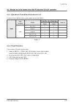
4-2-1 Operation of Power Block Protection Circuit
Protection Circuit operates when power problem occurs in the SMPS.
SMPS
Part
Location
Pin No.
Protection Circuit Operation
Remark
Open
Short
CN2
D5V (5, 6)
A5V (7)
-A5V (9)
-25V (11, 12)
+25V (15, 16)
<Table 4-1>
4-2-2 Power Protection
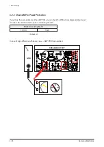
The Condition of Power Protection Active.
1. Voltage of SMPS’s +, - PVDD (+25V, -25V) is higher or lower than standards.
Normal Condition Voltage Range: PVDD (+25V, -25V): about +25V, -25V
2. Over-current occurs to FET. (Over-output or Output short)
3. FET’s temperature exceed 150°C.
4. No supply voltage on GATE DRIVER.
Summary of Contents for HW-C450
Page 16: ...3 4 Samsung Electronics MEMO ...
Page 35: ...Samsung Electronics 4 19 MEMO ...
Page 50: ...6 2 Samsung Electronics PCB Diagram 6 2 VFD PCB Top CN1 ...
Page 51: ...Samsung Electronics 6 3 PCB Diagram 6 3 VFD PCB Bottom ...
Page 52: ...6 4 Samsung Electronics PCB Diagram 6 4 KEY PCB Top ...
Page 53: ...Samsung Electronics 6 5 PCB Diagram 6 5 KEY PCB Bottom IC1 ...
Page 57: ...Samsung Electronics 6 9 PCB Diagram 6 7 MAIN PCB Bottom TP3 TP5 DIIC1 DSIC3 PWIC1 IC1 ...
Page 58: ...6 10 Samsung Electronics PCB Diagram 6 7 1 Test Point Wave Form TP3 TP5 ...
Page 59: ...Samsung Electronics 6 11 PCB Diagram 6 8 SMPS PCB Top 1 CN2 CN1 ...
Page 61: ...Samsung Electronics 6 13 PCB Diagram 6 9 SMPS PCB Bottom ...
Page 62: ...6 14 Samsung Electronics MEMO ...
Page 72: ...7 10 Samsung Electronics MEMO ...

