Samsung Electronics
4-1
Troubleshooting
4. Troubleshooting
4-1 Checkpoints by Error Mode
Oscilloscope Setting Values
Voltage/DIV
1V/div
TIME/DIV
500ms/div
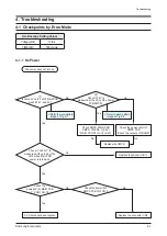
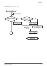
4-1-1 No Power
Yes
2
Check if 5.6V is
measured at the LA1 of the Power
PCB(SMPS).
Check SMPS, MAIN PCB
SMPS: CN2 No. 1 (5.6V)
MAIN: PCON1 No. 19 (5.6V)
Check the power circuit of
SMPS PCB
(Check the outputs of TRANS)
No
Yes
No
The power does not turn on.
AC Cable check and replace
Yes
Yes
Check if “H(3.3V)” is
measured at the pin 26 of the
UIC1 when Main PCB
power is turned on.
Replace the Micom (UIC1).
Replace the connector CN2.
No
Check the
power(3V) at MAIN PCB
P_CON1 NO.18
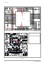
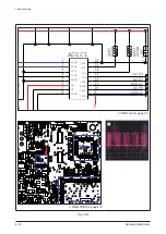
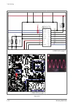
Refer to wave pattern
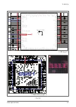
image of Fig. 4-1.
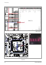
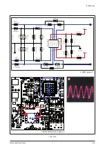
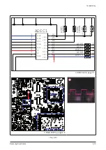
Refer to wave pattern
image of Fig. 4-2.
1
Is there 5V on the UIC1 Main PCB
pins #6,7,41, and 42?
Check the power(3V)
SMPS PCB CN2 NO.2
No
No
Replace the SMPS.
No
No
Summary of Contents for HW-C450
Page 16: ...3 4 Samsung Electronics MEMO ...
Page 35: ...Samsung Electronics 4 19 MEMO ...
Page 50: ...6 2 Samsung Electronics PCB Diagram 6 2 VFD PCB Top CN1 ...
Page 51: ...Samsung Electronics 6 3 PCB Diagram 6 3 VFD PCB Bottom ...
Page 52: ...6 4 Samsung Electronics PCB Diagram 6 4 KEY PCB Top ...
Page 53: ...Samsung Electronics 6 5 PCB Diagram 6 5 KEY PCB Bottom IC1 ...
Page 57: ...Samsung Electronics 6 9 PCB Diagram 6 7 MAIN PCB Bottom TP3 TP5 DIIC1 DSIC3 PWIC1 IC1 ...
Page 58: ...6 10 Samsung Electronics PCB Diagram 6 7 1 Test Point Wave Form TP3 TP5 ...
Page 59: ...Samsung Electronics 6 11 PCB Diagram 6 8 SMPS PCB Top 1 CN2 CN1 ...
Page 61: ...Samsung Electronics 6 13 PCB Diagram 6 9 SMPS PCB Bottom ...
Page 62: ...6 14 Samsung Electronics MEMO ...
Page 72: ...7 10 Samsung Electronics MEMO ...

