No
Yes
No
Yes
Check
T
e
m
p
S
ensor
connector
CN802
3&4P
I
N
on
DMD
Board
I
nstall
j
u
m
per
across
T
e
m
p
S
ensor
T
er
m
inals
Does
it
work?
Replace
T
e
m
p.
S
ensor
Re
insert
the
Connector
Replace
DMD
board
Do
fan(s)
run?
Does
color
wheel
run?
Replace
color
wheel
ass
y'
I
s
la
m
p
on?
Replace
DMD
Board
Check
220
~
410V
DC
to
la
m
p
ballast
(
x
1) Measure
with
DC
m
eter
Does
la
m
p
co
m
e
on
,
then
shut
off?
Replace
Power
Board
Re
-
install
la
m
p
ass
y'
Check
pin
1
on
CN803
on
DMD
board
for
5V
DC
Check
5Vpp
at
CN803
pin
1
on
DMD
Board
Replace
la
m
p
ass
y'
or
ballast
Replace
DMD
Board
Replace
ballast
or
la
m
p
ass
y'
Yes
No
No
No
No
Yes
Yes
Yes
Yes
No
No
Yes
No
No
No
Yes
Yes
T
e
m
perature
S
ensor
Replace
fan(s)?
Troubleshooting
6-2
Samsung Electronics
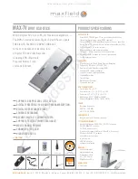
< Blinking Temp LED >
A blinking lamp LED is the most common failure indication. It can be caused by no lamp, no color wheel, no fan(s), or other
defective components.
www.fieldtechsource.net
Summary of Contents for HLS5087WX/XAA
Page 10: ...1 6 Samsung Electronics MEMO www fieldtechsource net ...
Page 44: ...3 28 Samsung Electronics MEMO www fieldtechsource net ...
Page 47: ...Samsung Electronics 5 2 MEMO www fieldtechsource net ...
Page 57: ...6 10 Samsung Electronics MEMO www fieldtechsource net ...
Page 65: ...7 8 Samsung Electronics MEMO www fieldtechsource net ...
Page 120: ...11 6 Samsung Electronics MEMO www fieldtechsource net ...
Page 144: ...12 24 Samsung Electronics MEMO www fieldtechsource net ...
Page 154: ...13 10 Samsung Electronics MEMO www fieldtechsource net ...