VCR Deck Operating Description
8-2
Samsung Electronics
8-3 Main Mechanism and Functions
8-3-1 Tape Path System
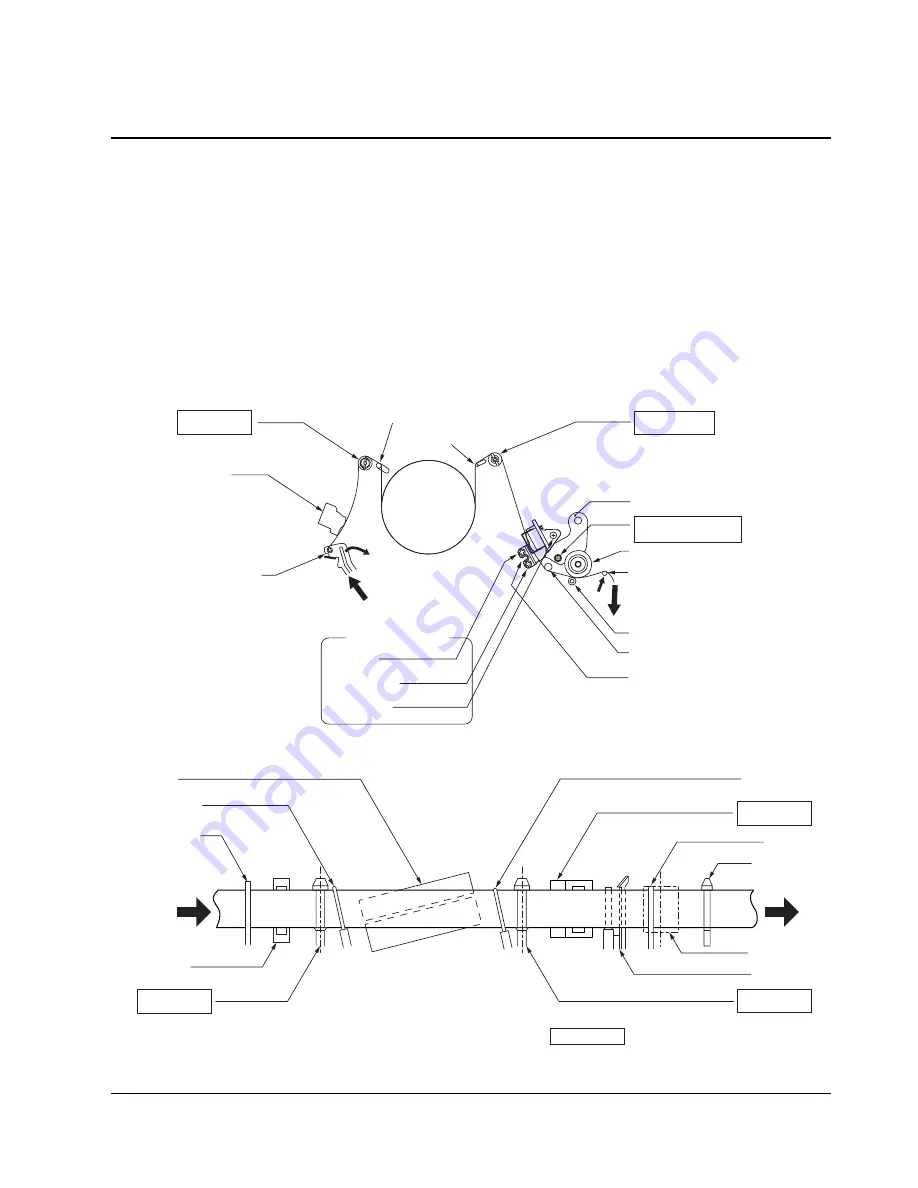
The tape come out from the supply reel (S) of the video cassette runs through paths shown in Figs. 8-2 and 8-3,
and is taken up by the take-up (T) reel. (S stands for the supply reel, and T for the take-up reel, hereafter.)
At S reel side (tape enterance side of the cylinder) against the cylinder, a tension post to allow the tape surface to
contact with each head with a proper tension which assures stable running, an FE head which erases entire data
of the tape, and an S guide roller which restricts tape motion in upward/downward direction are provided.
In the same way, a T guide roller, audio head to record audio signals at upper side of the tape, control head to
record and reproduce a control signal at lower side of the tape, and an audio erase head to erase only the audio
signals and perform after-recording in parallel with the audio head are provided at T reel side. (tape exit side of
the cylinder).
The guide parts marked with asterisks (*) are equipped with the adjusting mechanism to stabilize the tape run-
ning or to record and reproduce the signals precisely.
Fig. 8-2 Tape Path System
Cylinder
S guide roller
FE head
Tension lever
& tension post
S slant guide
T slant guide
T guide roller
ACE head position
adjusting screw
ACE head base
Pinch roller
No.9 guide
(pulled out at
RPS mode)
RPS
(released by
FF/REW mode)
Capstan motor
No.8 guide
ACE head position adjusting slit
(Insert slot-type screwdriver.)
Tilt
Azimuth
Height
ACE adjusting screw
*
*
*
*
Fig. 8-3 Guide Path System
Tension post
S slant guide
Cylinder
FE head
S guide roller
ACE head
T guide roller
T slant guide
Capstan
No.9 guide
Pinch roller
No.8 guide
show the locations to be adjusted.
*
*
*
*


