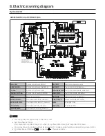
MAIN PBA
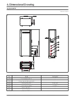
Printed circuit board (MAIN)
EEV TEMP
Electronic expansion valve
INVERTER PBA
Printed circuit board (INVERTER)
OLP TEMP
Thermistor (OLP_200kohm)
EMI PBA
Printed circuit board (EMI)
DISCHARGE TEMP
Thermistor (DISCHARGE_200Kohm)
CONTROL KIT PBA
Printed circuit board(CONTORL)
COND TEMP
Thermistor (COND_200Kohm)
COMP
Motor (compressor)
OUT TEMP
Thermistor (OUT_200Kohm)
WATER IN TEMP
Thermistor (WATER IN_10Kohm)
4-WAY VALVE
Solenoid valve (4 Way valve)
WATER OUT TEMP
Thermistor (WATER OUT_10Kohm)
FH152
FUSE (INV PCB)
EVA IN TEMP
Thermistor (EVA IN_10Kohm)
250V/40A
FUSE (EMI PCB)
EVA OUT TEMP
Thermistor (EVA OUT_10Kohm)
8. Electrical wiring diagram
Hydro Unit H
T
AM048CNBFCB/AA, AM072CNBFCB/AA
NOTE
• This wiring diagram applies only to the Indoor unit.
• Symbols show as follow :
BLK: black, RED: red, BLU: blue, WHT: white, YEL: yellow, BRN: brown, SKY: skyblue: GRN: green
• For connection wiring indoor-outdoor transmission F1-F2, indoor-wired remote controller transmission F3-F4.
•
Protective earth(screw),
: connector,
: The wire quantity

