background image

3-5

EB 01b_EN

February 2022 edition
Subject to technical changes

Design and principle of operation

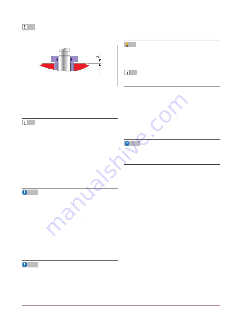
Do not tighten the stuf

fi

 ng box, the distance between the collar of 

the stuf

fi

 ng box and the bonnet 

fl

 ange must be 3 mm!

Figure

|

3-2: 

Adjustable stuf

fi

 ng box


Ö

Seal the stuf

fi

 ng box with a dot of red paint.

3.5.2  

 Assembly of the valve from DN

|

80 / 

NPS3, manufactured before 2006

The assembly of the valves up to DN 50 / NPS2 manufactured 
before 2006 is identical to the valves manufactured after 2006, 
see Chapter 3.5.1

3.5.2.1  Valve body assembly


Ö

Clamp the valve body (1) with the 

fl

 ange in a vice so that the 

bearing area of the seat is easily reached.


Ö

Screw in the PTFE seat (3) using a suitable special tool into 
the thread of the body (1). For the tightening values of the 
seat, see Table 15-2 in Chapter “15.1.1 Tightening torques”.

Damage to the valve due to improper assembly

The thread on the seat and in the valve are delicate and can be 
damaged


Ö

Do not twist the seat when screwing in and do not damage 
the thread.


Ö

Rework the seat inner diameter to size.

3.5.2.2  Assembly of the stem


Ö

Push the retainer ring (22) from the short thread side into the 
groove of the stem (12).

Damage to the parts of the stem sealing in contact with media 
due to unsuitable grease.


Ö

When assembling the stem, bellows, plug and all other parts 
of the stem sealing in contact with media, only use water-free 
grease (e. g. halocarbon).

Info

Info

NOTE

NOTE


Ö

Grease the stem (12) on the bottom thread.


Ö

Screw the bellows (5) with a preassembled washer and bush-
ing onto the greased thread of the stem (12).

Due to the sliding property of the PTFE, we recommend using em-
ery cloth to prevent the bellows from sliding when screwing it on-
to the stem.

To make it easy to push on the plug stem, make a small notch in 
the bellows to let air escape.


Ö

Push the plug (4) onto the bellows (5).


Ö

Secure the connection between the plug and bellows with a 
PTFE cord (6) inserted as far as possible. Use a sharp knife to 
cut off the remaining part of the cord that projects.

3.5.2.3 Assembly of the bonnet 

fl

 ange


Ö

Clamp the bonnet 

fl

 ange (2) with the stem guide facing down 

in a vice.

Damage to the bonnet 

fl

 ange due to improper handling!


Ö

Do not damage the bonnet 

fl

 ange, especially the thread on 

the stem end.


Ö

Apply Loctite on the Glycodur bushings (27 and 28).


Ö

Insert the Glycodur bushing (27) with a suitable pin as far as 
possible into the stem guide.


Ö

Push in the Glycodur collar bushing (28) as far as possible.


Ö

For further assembly, place the bonnet 

fl

 ange (2) with the 

fl

 ange side on a clean surface at a working height so that the 

upper opening is easy to reach.


Ö

Push in the V-ring packing (15) V-pressure ring, PTFE V-rings 
and 

fi

 nal ring in the correct order into the intended bore. Re-

fer to the drawing Figure 3-3 for the arrangement of the 
V-ring packing.


Ö

Insert the set of spring washers (16). Refer to the drawing 
Figure 3-3 for the arrangement of the spring washers.

Tip

Info

NOTE

Summary of Contents for EB 01b

Page 1: ...Phone 49 2152 2005 0 Fax 49 2152 1580 sales pfeiffer de samsongroup com www pfeiffer armaturen com MOUNTING AND OPERATING INSTRUCTIONS EB 01b Translation of the original manual Control valve BR 01b D...

Page 2: ...or safe and correct use read this EB carefully prior to use and keep it for later reference In the case of questions that go beyond the scope of this EB please contact the After Sales Service at PFEIF...

Page 3: ...3 3 3 5 1 Valve assembly manufactured after 2006 3 3 3 5 2 Assembly of the valve from DN 80 NPS3 manufactured before 2006 3 5 4 Shipment and on site transport 4 1 4 1 Accepting delivery 4 1 4 2 Unpack...

Page 4: ...11 1 Removing the valve from the pipe 11 1 11 2 Disassembling the actuator 11 1 12 Repairs 12 1 12 1 Replacing the bellows 12 1 12 2 Replacing the bellows and the packing 12 1 12 3 Adjusting the stuf...

Page 5: ...ualified specialist personnel trained in pres surised pipes who are familiar with the assembly commissioning and operation of this product Specialist personnel in terms of this installation and operat...

Page 6: ...the directive for all metal parts in po tentially explosive areas Valves with plastic lining PFA PTFE through which chargea ble media flows during operation must be provided with an electrostatically...

Page 7: ...g normal operation in particular with gaseous hot and or hazardous media spraying medium can cause hazards It must be kept in mind that the media is usually hazardous A blind flange must be assembled...

Page 8: ...orrode and damage the surface The valve material requires suitable lubricants see Chapter 15 1 2 Lubricants 1 4 Warning notes on the device Warning of moving parts Figure 1 1 Warning of moving parts T...

Page 9: ...234 001 001 Valve no within the item Item in the order Order Year of manufacture 38 2018 39 2019 30 2020 31 2021 etc Manufacturer number 2009 to 2017 e g 211234 001 001 21 1234 001 001 Valve no within...

Page 10: ...1 Valve type plate Figure 2 1 Marking positions of the type plate on the valve BR 01b 2 1 2 Actuator type plate See the corresponding actuator documentation 2 2 Material marking The valves are marked...

Page 11: ...springs Valve with fail open actuator Upon air failure the valve is opened The valve closes when the signal pressure increases acting against the force of the springs Changing the fail safe position T...

Page 12: ...Parts list Pos Designation Pos Designation 1 Valve body 14 Distance bush 2 Bonnet flange 15 V ring packing 3 Seat 16 Set of spring washers 4 Plug 17 Bearing bush 5 Bellows 18 O ring 6 Cord 19 Stuffing...

Page 13: ...cturer Fuchs to prevent the cold welding of the screws in the bodies Do not use this product for valves with use of oxygen A suit able lubricant must be selected for grease free valves espe cially for...

Page 14: ...readed bushing due to improper assembly The threaded bushing must not be inserted at a slanted angle when screw it into the bonnet flange Info Info NOTE NOTE Only for DN 80 and DN 100 push the yoke 25...

Page 15: ...a only use water free grease e g halocarbon Info Info NOTE NOTE Grease the stem 12 on the bottom thread Screw the bellows 5 with a preassembled washer and bush ing onto the greased thread of the stem...

Page 16: ...2006 Table 3 2 Parts list Pos Designation Pos Designation 1 Valve body 17 Bearing bush 2 Bonnet flange 18 O ring 3 Seat 19 Stuffing box 4 Plug 20 Screw 5 Bellows 21 Nut 6 Cord 22 Retainer ring 7 O rin...

Page 17: ...vice with the bonnet opening facing upwards Place the preassembled bonnet flange see chapter 3 5 2 4 onto the valve body carefully Insert the screws 20 and align using the nuts 21 Tighten the screws e...

Page 18: ...3 8 EB 01b_EN February 2022 edition Subject to technical changes Design and principle of operation...

Page 19: ...equipment and load lifting equip ment whose lifting capacity corresponds at least to the weight of the valve including the actuator Take the weights from the respective data sheet Danger of injury due...

Page 20: ...ansporting the valve can change how ever The operator makes sure that the valve is lifted and transport ed safely Lifting the valve Fasten a lifting sling to each flange of the housing and on the susp...

Page 21: ...packaging should protect the scratch sensitive plastic lin ing of the valve against damage Valves that weigh more than approx 10 kg should be stored on a pallet or supported similarly Valves are usual...

Page 22: ...4 4 EB 01b_EN February 2022 edition Subject to technical changes Shipment and on site transport...

Page 23: ...n be released to the outside protection against over pressure in the device Furthermore vents allow the intake of air protection against underpressure in the device Carry out venting on the side that...

Page 24: ...nd stops is the responsibility of the user 5 3 1 Travel adjustment with separately sup plied SAMSON actuator With a separately supplied valve and SAMSON actuator the di mension H from the upper edge o...

Page 25: ...itable pretension that implements the sealing between the seat and the plug Table 5 3 Actual travel Travel 15 mm Actual travel 16 to 17 mm Travel 30 mm Actual travel 31 to 32 mm 5 4 Installing the val...

Page 26: ...the intake of air protection against underpressure in the device Carry out venting on the side that faces away from the work ing area of operating personnel When installing peripheral devices make su...

Page 27: ...alve open The test pressure may not exceed the value 1 5 x PN according to the type plate or the marked test pressure PT If a valve leaks observe chapter 8 Faults The plant operator is responsible for...

Page 28: ...5 6 EB 01b_EN February 2022 edition Subject to technical changes Installation...

Page 29: ...tion Danger of injury due to escaping exhaust air During operation when regulating or when opening and closing the valve exhaust air can escape for example from the actuator Wear eye protection when...

Page 30: ...6 2 EB 01b_EN February 2022 edition Subject to technical changes Start up...

Page 31: ...ocumentation Danger of injury due to escaping exhaust air During operation when regulating or when opening and closing the valve exhaust air can escape for example from the actuator Wear eye protectio...

Page 32: ...7 2 EB 01b_EN February 2022 edition Subject to technical changes Operation...

Page 33: ...ion loosened Retighten the flange connection with the respective tightening torque see Table 1 in Chapter 15 1 1 Tightening torques Body parts untight after retightening Replace the body sealing and o...

Page 34: ...ons see Chapter 12 Repairs Malfunction The actuator unit or control does not react Check the actuator unit and control command The actuator and control are OK Remove and inspect the valve see chapter...

Page 35: ...em operator is responsible for emergency measures In case of a valve fault Close the valves upstream and downstream of the valve so that no medium flows through the valve Troubleshoot the error see ch...

Page 36: ...8 4 EB 01b_EN February 2022 edition Subject to technical changes Malfunction...

Page 37: ...ngs before working on the actuator see the corresponding actuator documentation Danger of injury due to residual medium in the valve When working on the valve residual medium can escape and depending...

Page 38: ...efore all maintenance work see Chapter 12 Repairs After all maintenance work the valve must be checked prior to recommissioning see Chapter 5 5 Checking the mounted valve 9 2 1 Replacing the seat and...

Page 39: ...stem If the actuator stem and stem are blocked e g due to seizure if not actuated for a long period of time release the residual energy of the actuator spring tension before releasing the blockage se...

Page 40: ...10 2 EB 01b_EN February 2022 edition Subject to technical changes Decommissioning...

Page 41: ...idual medium can escape and depending on the medium properties cause injuries e g scald ing chemical burns Wear protective garments protective gloves and eye protec tion Do not loosen the test connect...

Page 42: ...11 2 EB 01b_EN February 2022 edition Subject to technical changes Removal...

Page 43: ...Chapter 3 5 1 and Chap ter 3 5 2 12 2 Replacing the bellows and the packing If the stuffing box is not tight the packing and the bellows can be defective Check the condition of the packing and the be...

Page 44: ...12 2 EB 01b_EN February 2022 edition Subject to technical changes Repairs Figure 12 2 Section diagram of valve BR 01b...

Page 45: ...Clamp the valve with the stem guide facing up in a vice Release the screws 20 and depending on the design the nuts 21 Carefully lift the bonnet flange up off the valve body and place it on a clean eve...

Page 46: ...inal size and version of the valve Manual valve automated valve Medium designation and consistency Medium pressure and temperature Flow rate in m h Bench range of the actuator e g 0 2 to 1 bar Number...

Page 47: ...y 2022 edition Subject to technical changes Disposal 13 Disposal For disposal observe the local national and international regulations Do not dispose of old components lubricant and hazardous material...

Page 48: ...13 2 EB 01b_EN February 2022 edition Subject to technical changes Disposal...

Page 49: ...formity according to Pressure Equipment Directive 2014 68 EU for manually operated valves see page 14 3 Declaration of conformity for completed machinery accord ing to Machinery Directive 2006 42 EC f...

Page 50: ...14 2 EB 01b_EN February 2022 edition Subject to technical changes Certificates...

Page 51: ...14 3 EB 01b_EN February 2022 edition Subject to technical changes Certificates...

Page 52: ...14 4 EB 01b_EN February 2022 edition Subject to technical changes Certificates...

Page 53: ...14 5 EB 01b_EN February 2022 edition Subject to technical changes Certificates...

Page 54: ...14 6 EB 01b_EN February 2022 edition Subject to technical changes Certificates...

Page 55: ...m 50 2 approx 10 Nm 80 3 approx 30 Nm 100 4 approx 50 Nm 150 6 on request 15 1 1 3 Flange connections Table 15 3 Tightening values for the DIN flange connections DN mm 15 25 40 50 80 100 150 MA Nm 1 2...

Page 56: ...15 2 EB 01b_EN February 2022 edition Subject to technical changes Annex 15 2 1 Spare parts for valves manufactured after 2006 Figure 15 1 Exploded drawing of the valve manufactured after 2006...

Page 57: ...ge EN JS 1049 3 Seat PTFE 4 Plug PTFE 5 Bellows PTFE 6 Cord PTFE 7 O ring EPDM 8 Thrust washer 1 4305 9 Spring washer 1 8159 Delta Tone 10 Guide bush 1 4305 11 Bearing bush PTFE with carbon 12 Stem 1...

Page 58: ...15 4 EB 01b_EN February 2022 edition Subject to technical changes Annex 15 2 2 Spare parts for valves manufactured before 2006 Figure 15 2 Exploded drawing of the valve manufactured before 2006...

Page 59: ...PTFE 4 Plug PTFE 5 Bellows PTFE 6 Cord PTFE 7 O ring EPDM 8 Thrust washer 1 4305 9 Spring washer 1 8159 Delta Tone 10 Guide bush 1 4305 11 Bearing bush PTFE with carbon 12 Stem 1 4571 13 Locking scre...

Page 60: ...ize and version of the valve Manual valve automated valve Medium designation and consistency Medium pressure and temperature Flow rate in m h Bench range of the actuator e g 0 2 to 1 bar Number of act...

Page 61: ...EB 01b_EN February 2022 edition Subject to technical changes...

Page 62: ...EB 01b_EN February 2022 edition Subject to technical changes...

Page 63: ...EB 01b_EN February 2022 edition Subject to technical changes...

Page 64: ...2022 edition Subject to technical changes PFEIFFER Chemie Armaturenbau GmbH Hooghe Weg 41 47906 Kempen Phone 49 2152 2005 0 Fax 49 2152 1580 E Mail sales pfeiffer de samsongroup com Internet www pfei...

Reviews: