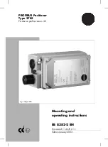
1. Design and principle of oper-
ation
The digital PROFIBUS PA positioner is at-
tached to pneumatic control valves. It as-
signs the valve position (controlled variable)
to the control signal (reference variable).
The positioner compares the digital control
signal transmitted from the control equip-
ment to the travel of the control valve and
issues a pneumatic signal pressure (output
variable). To do so, a supply air pressure of
1.4 to 6 bar is required. The electric power
is supplied by the bus connection of the
PROFIBUS PA segment in accordance with
IEC 61158-2 regulations.
The positioner consists of an inductive, fric-
tionless displacement sensor system and an
electrically controlled valve block with two
on-off valves, as well as the electronics in-
cluding the two microcontrollers to edit the
control algorithm and manage PROFIBUS
communication.
When a system deviation occurs while com-
paring set point and actual value, the micro-
controller returns binary pulse-pause-modu-
lated signals which are used to control two
on-off valves with subsequent boosters. One
valve controls the exhaust air, the other the
supply air.
The supply air valve (3) connects the supply
air (7, supply air pressure 1.4 to 6 bar) and
the actuator (filling). The exhaust air
valve (4) connects the actuator and the at-
mosphere (venting). These on-off valves can
either have the switching states continuously
open or continuously closed, or they can
generate single pulses of variable width.
Controlling the two valves causes the actua-
tor of the control valve to move the plug
stem to a position corresponding to the ref-
erence variable. If there is no system devia-
tion, both the exhaust and supply air valves
are closed.
By default, the positioner is equipped with a
binary input for floating contacts, which
serves to signalize the switching state of an
additional field device via PROFIBUS.
The write protection switch in the hinged
cover (located near the bus address adjust-
ment) prevents that positioner settings are
overwritten via PROFIBUS communication
on activation.
Positioner with forced venting function:
The positioner is controlled by a 6 to 24 V
signal, causing the signal pressure to be ap-
plied to the actuator. When this voltage sig-
nal decreases, the signal pressure is shut off
and the actuator is vented. Additionally, the
control valve is moved to its fail-safe posi-
tion by the integrated springs.
All positioners are equipped with the forced
venting function, which can be activated
and deactivated using a switch (also see sec-
tion 4.3).
1.1 Options
The standard positioner version can be sup-
plemented with limit switches. Two
proximity switches suitable for fail-safe cir-
cuits can be used to signalize the valves
final positions.
1.2 Communication
The positioner is completely controlled via
digital signal transmission according to
PROFIBUS PA Profile Class B based on
DIN EN 50170 and DIN 19245 Part 4.
Data is transmitted as bit synchronous cur-
rent modulation with a transfer rate
10
EB 8382-2 EN
Design and principle of operation
Summary of Contents for 4785
Page 73: ...EB 8382 2 EN 73...
Page 74: ...74 EB 8382 2 EN...
Page 75: ...EB 8382 2 EN 75...
Page 76: ...76 EB 8382 2 EN...
Page 77: ...EB 8382 2 EN 77...


