


14
EB 8091-1 EN
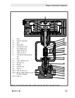
Design and principle of operation
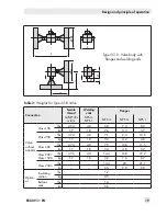
3.2 Versions
The modular design allows an insulating sec-
tion or metal bellows to be fitted to the stan-
dard valve version.
If valve accessories (e.g. positioner, limit
switch etc.) are to be mounted to the valve
version with flanges, we recommend mount
-
ing an insulating section or bellows seal. This
provides more space to mount valve accesso-
ries.
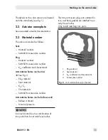
Actuators
In these instructions, the preferable combina-
tion with a Type 3271 or Type 3277 Pneu-
matic Actuator is described. The pneumatic
actuator (with or without handwheel) can be
replaced by another pneumatic actuator in a
different size, but with the same travel.
Î
Observe the maximum permissible actu-
ator force.
If the travel range of the actuator is larger
than the travel range of the valve, the spring
assembly in the actuator must be preloaded
so that the travel ranges match. See associ-
ated actuator documentation.
The basic pneumatic actuator can be re-
placed by a pneumatic actuator with addi-
tional handwheel or by an electric actuator.
3.3 Technical data
The nameplates on the valve and actuator
provide information on the control valve ver-
sion. See section 2.1 and the actuator docu-
mentation.
More information is available in Data Sheet
u
T 8091-1.
Compliance
The Type 3510 Valve bears the EAC mark of
conformity:
Temperature range
Depending on the version, the control valve
is designed for a temperature range from 14
to 428 °F (–10 to +220 °C). The use of an
insulating section or bellows seal extends the
temperature range from –325 to +842 °F
(–196 to +450 °C). Special materials are
available for temperatures up to 1200 °F
(650 °C).
Leakage class
Depending on the version, the following
leakage class according to ANSI/FCI 70-2
or IEC 60534-4 applies:
−
Leakage class IV with metal seal
−
Leakage class V for high-performance
metal seal
Tip
Note
Note
Summary of Contents for 3510
Page 29: ...EB 8091 1 EN 29...


