background image

DATOS TÉCNICOS

BGW100

BGW200

ELÉCTRICO

Alcance de la tensión de entrada

6 … 35 V

Corriente de salida máxima continua (@25 °C)

100 A

200 A

Corriente de pico (@25 °C)

500 A (±0.6 sec)

1200 A (±0.7sec)

Caída de tensión

50 mV @ 100 A

50 mV @ 200 A

Consumo de corriente Salida en activo

3,2 mA

Consumo de corriente Salida en inactivo

3,2 mA

Precisión de la tensión

2%

Precisión de la corriente

10%

Carga máxima de salida de alarma

100 mA

CONEXIÓN ENTRADA Y SALIDA

Grosor mínimo de los hilos del cable

35 mm

2

50 mm

2

Tamaño de perno

M8

M10

Terminales de cable

Los terminales de cable son aptos para el 

diámetro de cable utilizado.

CONEXIONES FASTON

Grosor mínimo de los hilos del cable

1,5 mm

2

Enchufe Faston

6,3 mm

MECÁNICO

Orificio de montaje (Ø)

4,5 mm

Distancia entre el orificio de montaje y 
(distancia de centro a centro) ± 1 mm

60 mm

100 mm

Peso

190 g

295 g

Dimensiones (Al*An*Pr) ± 1 mm

34*72*73 mm

39*76*111 mm

Código IP

IP66

Material de carcasa

PU552

Color de la carcasa

Negro

Modelo de enfriamiento

Convección y conducción.

GENERAL

Temperatura ambiental de funcionamiento

-10 °C  ... +40 °C

Temperatura de almacenamiento

-25 °C  ... +85 °C

Humedad ambiental de funcionamiento

Hasta 95%, sin condensación.

Aislamiento galvánico

No

Apagar contacto por control remoto

PROTECCIÓN

Sobrecorriente/Cortocircuito

Sí (reinicio después de 1 minuto).

Sobrecalentamiento, desactivación

A más de 85 °C (reinicio después de 1 minuto).

Protección de polaridad

Sí, con fusible en la línea min (–).

Summary of Contents for BGW 100

Page 1: ...100 BGW 200 Battery Guard Waterproof BATTERY GUARD WATERPROOF Please read this manual before operating your Battery Guard Owners Manual Gebruiksaanwijzing Bedienungsanleitung Mode D Emploi Manual del...

Page 2: ...voltage threshold undervoltage reset overvoltage threshold and overvoltage reset can be set by the user Please see CONFIGURE Programming how to set these values Undervoltage If the BGW s input voltage...

Page 3: ...y short again to set the correct position from the programming table The LED will light up as feedback At that point program position 1 is selected The user can briefly short make the connection again...

Page 4: ...TON CONNECTIONS Minimum wire diameter 1 5 mm2 Faston plug 6 3 mm MECHANICAL Mounting hole 4 5 mm Distance between mounting holes centre to centre 1 mm 60 mm 100 mm Weight 190 g 295 g Dimensions H W L...

Page 5: ...SCHEMA zie laatste bladzijde WERKING Ingangsspanningsbeveiliging De waarden van de ingangsspaningsbeveiliging onderspanning drempel onderspanning reset overspanning drempel en overspanning reset zijn...

Page 6: ...knipperen Zodra dit gebeurd is moet de verbinding verbroken worden Om het juiste positienummer in te stellen moet dezelfde verbinding weer kort gemaakt worden de led zal als terugkoppeling oplichten...

Page 7: ...te kabeldiameter AANSLUITINGEN FASTON Minimale aderdikte 1 5 mm2 Faston stekker 6 3 mm MECHANISCH Montagegat 4 5 mm Afstand tussen montagegaten hart op hart 1 mm 60 mm 100 mm Gewicht 190 g 295 g Dimen...

Page 8: ...Anschluss ein 1 5 mm2 Kabel mit 1A Sicherung f r das BGW100 und 5A Sicherung f r das BGW200 von der Batterie zum BGW Diesen Anschluss nur f r die BGW verwenden SCHALTPLAN SIEHE LETZTE SEITE FUNKTIONS...

Page 9: ...ogrammierungsmodus zu aktivieren muss eine Verbindung zwischen Programmeingang CONFIG und Minus Anschluss hergestellt werden 2 Sekunden nach der Herstellung der Verbindung blinkt die LED einmal auf Gl...

Page 10: ...ON STECKERANSCHL SSE Mindestquerschnitt 1 5 mm2 Faston Stecker 6 3 mm MECHANISCH Montageloch 4 5 mm Abstand zwischen Montageloch und Mittelpunkt zu Mittelpunkt 1 mm 60 mm 100 mm Gewicht 190 g 295 g Ab...

Page 11: ...le 1A pour le BGW100 et un fusible 5A pour le BGW200 de la batterie au BGW pour la connexion n gative Utilisez cette connexion uniquement pour le BGW SCH MA DES CONNEXIONS Veuillez consulter la derni...

Page 12: ...e de programmation il faut tablir un contact entre l entr e de CONFIG et la borne n gative La LED 1 se met clignoter d s qu un contact a t tabli pendant 2 secondes D s que cela se produit le contact d...

Page 13: ...ENTS FASTON paisseur minimale d me 1 5 mm2 Connecteur Faston 6 3 mm M CANIQUE Orifice de montage 4 5 mm Distance entre les orifices de montage centre centre 1 mm 60 mm 100 mm Poids 190 g 295 g Dimensi...

Page 14: ...W200 conectado directamente desde la bater a al BGW Utilice esta conexi n solo para BGW ESQUEMA DE CONEXI N Por favor vea la ltima p gina FUNCIONAMIENTO Protecci n de la tensi n entrada El usuario pue...

Page 15: ...GURAR PROGRAMACI N Para iniciar el modo de configurar programaci n debe establecerse una conexi n entre la entrada de CONFIG y el min Una vez se haya establecido la conexi n durante 2 segundos el LED...

Page 16: ...ONES FASTON Grosor m nimo de los hilos del cable 1 5 mm2 Enchufe Faston 6 3 mm MEC NICO Orificio de montaje 4 5 mm Distancia entre el orificio de montaje y distancia de centro a centro 1 mm 60 mm 100...

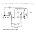
Page 17: ...WIRING DIAGRAM AANSLUITSCHEMA SCHALTPLAN SCH MA DES CONNEXIONS ESQUEMA DE CONEXI N 1A fuse for the BGW100 and 5A fuse for the BGW200 FUSE...

Page 18: ...07 BA ZAANDAM The Netherlands Declares that the following products PRODUCT TYPE Battery Guard Waterproof BRAND Samlex Standards to which conformity is declared EN 61000 6 2 2005 EN 61000 6 3 2007 Sign...

Page 19: ...BGW 100 200 170123 www samlex com www samlex solar com...

Reviews: