Operating manual
Tractor mounted snow plow
Smart (K), Lite 150, Uni
-
14
-
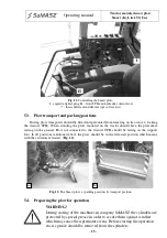
Fig. 10.
Mounting the Smart plow on the three point hitch (A – pins with cotter pins,
B – hydraulic connections, C – support foot, D – electrical cable,
E – tractor's lower arms, F – upper tie, G - turning axis of the moldboard)
In order to mount the plow on the tractor approach the plow so that the lower lifting arms of
the three point hitch are inserted into the mountings of the plow's suspension, secure the mounting
using pins and cotter pins. Connect the upper part of the suspension system using a regulated tie
and secure them with pins and cotter pins (
Fig. 10
). Next, connect the hydraulic connections and
the power plug along with the control switch. The rotation axis of the moldboards should be
perpendicular to the ground. After lifting the plow the support foot should be lifted and secured
with a pin. If the plow has been equipped with support wheels or skids they should be adjusted to
the correct height.
WARNING!
The manufacturer is not responsible for damages to the device
resulting from improper mounting of the plow on the TPH of the
tractor. During operation periodically check weather the plow is still
properly mounted.
5.2.
Plow control
After connecting the hydraulic system (
B
) (
Fig. 10
) take the electrical cable (
D
) (
Fig. 10
)
into the tractor's cabin and insert the plug into the 12 V cigarette lighter outlet (
I
) (
Fig. 11
).
In order to lift/lower the plow we use the control lever (
H
) of the front TPH of the tractor.
To rotate the moldboard, use the hydraulic control lever (
H
) (
Fig. 11
). Turn the marker lights on
or off insert or remove the electrical cable plug from the cigarette lighter outlet.
A
D
B
C
E
90°
F
G


