STB8827
Series Operation Manual Chapter 1 Out of Box Audit
1.7
3
Other features
1) Power: consumption power
≤
80VA.
2) Dimension (W*H*D): 430mm*185mm*473mm 3) Weight: About 13kg.
Page 1: ...O OP PE ER RA AT TI IO ON N M MA AN NU UA AL STB8827 Series P P Pr r re e ec c ci i is s si i io o on n n L L LC C CR R R M M Me e et t te e er r r Saluki Technology Inc...
Page 2: ...responding displayed pages 8 2 4 1 MEAS 8 2 4 2 SETUP 9 2 4 3 SYSTEM 9 2 5 Basic Operation 9 2 6 Start the instrument 9 Chapter 3 Introduction to MEAS 11 3 1 MEAS DISPLAY 11 3 1 1 Test function 11 3 1...
Page 3: ...value of tolerance mode 39 3 7 4 Comparator function ON OFF 39 3 7 5 Auxiliary bin ON OFF 39 3 7 6 HIGH LOW 40 3 8 LIST SWEEP SETUP 41 3 8 1 MODE 42 3 8 2 Test parameter 42 3 8 3 Sweep parameter setu...
Page 4: ...xample of comparator 62 5 7 1 Capacitor sorting 63 5 8 Operation example of load correction 64 Chapter 6 Performance and Test 66 6 1 Test function 66 6 1 1 Parameter and symbol 66 6 1 2 Equivalent mod...
Page 5: ...subsystem commands 82 7 1 3 VOLTage subsystem commands 83 7 1 4 CURRent subsystem commands 83 7 1 5 AMPLitude subsystem commands 84 7 1 6 Output RESister subsystem commands 84 7 1 7 OUTPut subsystem c...
Page 6: ...s of the instrument and our company is subject to change and to improve the performance function inner structure appearance accessory and package of the instrument without notice If there is puzzle ca...
Page 7: ...on the rear panel 2 Power supplying frequency range 47 63Hz 3 Power supplying power range less than 80VA 4 Power supplying input phase line L zero line N ground lead E should be as same as the power p...
Page 8: ...ween 5 and 40 humidity is less than 85 RH If the instrument will not be put in use for a time please have it properly packed with its original box or a similar box for storing 6 The instrument especia...
Page 9: ...STB8827 Series Operation Manual Chapter 1 Out of Box Audit 1 7 3 Other features 1 Power consumption power 80VA 2 Dimension W H D 430mm 185mm 473mm 3 Weight About 13kg...
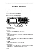
Page 10: ...RESET KEYLOCK DC BIAS DC SOURCE PASS FAIL TRIGGER HCUR LOG STB8827C Precision LCR Meter 20Hz 1MHz 1 20 19 6 9 15 14 18 2 17 16 7 10 23 22 21 8 11 12 13 3 4 5 Figure 2 1 Front panel 1 Brand and model B...
Page 11: ...terminals UNKNOWN 4 teminal test pair is used to connect 4 terminal test fixture or cable to measure DUT The 4 terminals are respectively as follows Hcur Hpot Lpot and Lcur 15 Ground terminal The grou...
Page 12: ...y when discharging the key lock or the key cannot be unlocked When the instrument is controlled by RS232 KEYLOCK will be lighted Press KEYLOCK again it will be off which means returning to the local d...
Page 13: ...rface The tester can communicate with PC through GPIB interface 6 Ground terminal The ground terminal is connected with instrument casing being available for protecting or shielding ground connection...
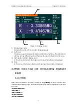
Page 14: ...f cursor s direction in the zone 3 Test result condition display zone In this zone test result information and current condition are displayed 4 Help In this zone information about system and user dat...
Page 15: ...unctions corresponding to the current zone of the cursor will be displayed in the soft key zone Users can select and use the desired key Numeric keys and ENTER are used to input data When a numeric ke...
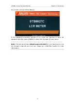
Page 16: ...f the password protection function is on users are required to input the password and then press ENTER to enter into the page of main menu Note The instrument has a default password 2827 In your pract...
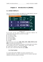
Page 17: ...quency FREQ Test level LEVEL Test range RANGE Test speed SPEED DC BIAS There are 6 zones in this page FUNC FREQ LEVEL RANG SPEED and DC BIAS The details will be discussed later The test result conditi...
Page 18: ...larity M Mutual inductance R2 DC resistance Test results of primary and secondary parameters are respectively displayed in two lines in the form of upper case characters The primary parameter displays...
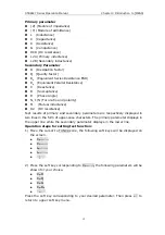
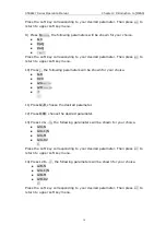
Page 19: ...nding to your desired parameter Then press to return to upper soft key menu 5 Press Ls the following parameters will be shown for your choice Ls D Ls Q Ls Rs Press the soft key corresponding to your d...
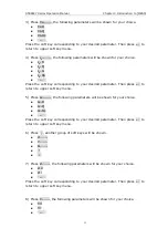
Page 20: ...ress the following parameters will be shown for your choice G B DCR L2A L2B 11 Press G B choose the desired parameter 12 Press DCR choose the desired parameter 13 Press L2A the following parameters wi...
Page 21: ...decrease the range under HOLD mode 2 Use soft keys to set measurement range 3 1 3Test frequency The measurement range of STB8827 ranges from 20Hz to 1MHz with an increase or decrease of 0 01Hz When th...
Page 22: ...frequency The selectable frequencies are the same as that of 2 Use soft keys or numeric keys to select or set frequency When using numeric keys to input the required frequency value the soft key disp...
Page 23: ...ys 1 Move the cursor to LEVEL the following soft keys will be displayed This soft key is used to increase the level of test signal source This soft key is used to decrease the level of test signal sou...
Page 24: ...ermined by the following factors Integration time A D conversion Average times average test times per each test Measurement delay from startup to the start of measurement Display time of test results...
Page 25: ...decrease the displayed digit by ten times NOTE Under the following circumstance the function of decimal lock will be cancelled automatically to recover to floating decimal point status Test function i...
Page 26: ...r of secondary bin limit If the primary parameter of DUT is within the range of the bin limit but the secondary parameter is outside of the bin limit the DUT will be sorted into the auxiliary bin When...
Page 27: ...ers can set them on the LIMIT TABLE SETUP page Test parameter PARAM Nominal value NOM Bin limit value HIGH LOW 3 3 1PARAM Parameter zone shows the Function parameter if user selects primary and second...
Page 28: ...N OFF RESET 2 Press the soft key ON to turn on the count function 3 Press the soft key OFF to turn off the count function 4 Press the soft key RESET Reset count Sure will be displayed in the help zone...
Page 29: ...can make automatic sweep test for up to 201 points test frequencies test levels or DC bias Two sweep modes are available on STB8827 SEQ and STEP In SEQ mode each press of TRIGGER will direct STB8827 t...
Page 30: ...st 3 4 3 R X This zone is the currently swept Function parameter and its unit What are right below this item are the sweep results 3 4 4CMP Compare This zone indicates the compare results of the curre...
Page 31: ...t frequency FREQ Test level LEVEL Test range RANGE Test speed SPEED DC Bias DC BIAS DC Voltage Source DC SRC 3 5 1Trigger mode There are 4 trigger modes on STB8827 INT MAN EXT and BUS When the trigger...
Page 32: ...constant level function is valid if the level exceeds above ranges this function will be automatically set as OFF The level value currently set is generally deemed as non constant level value Operatio...
Page 33: ...cursor to ISO zone the following soft keys will be displayed ON OFF 2 Press ON to turn on the bias current isolation function 3 Press OFF to turn off the bias current isolation function 3 5 4Average...
Page 34: ...27 trigger delay means the delay time from triggering to test start Delay function can set the trigger delay time When the list sweep test function is used all set delay time will be delayed at each s...
Page 35: ...S Absolute Deviation mode The deviation currently displayed is the difference between the test value of the DUT and the preset reference value The formula of calculating ABS is as below ABS X Y Where...
Page 36: ...tion mode of the primary parameter 7 Move the cursor to the DEV B zone the following soft keys will be displayed ABS OFF 8 Use above soft keys to se the deviation mode of the secondary parameter 3 6 C...
Page 37: ...e similar with the setting zones but the monitoring zones can only provide information and you cannot change state or parameter of these zones except REF A and REF B The real test results of load corr...
Page 38: ...s open and not connecting to any DUT 3 Press MEAS OPEN STB8827 will test the open admittance capacitance andinductance under 48 frequencies It will take about 75 seconds to finish the open full freque...
Page 39: ...kHz 43 points the highest test frequency of STB8827B is 500kHz 45 points the highest test frequency of STB8827C is 1MHz 48 points The calibration point can be set in SPOT No on CORRECTION and then the...
Page 40: ...e at the preset frequency FREQ the load correction of STB8827 can eliminate the test error It is obvious that open short and load correction can be performed at preset frequencies The preset frequenci...
Page 41: ...t preset frequency The test result R X of the short correction will be displayed in the help line the bottom line 12 Move the cursor to SHORT 13 Press ON to perform the short correction calculation at...
Page 42: ...ng figure shown STB8827307 Compare function can be set on this page STB8827 can set 9 bin limits of primary parameters and one of secondary parameters The tested result can be divided into up to 10 bi...
Page 43: ...parameters 1 Move the cursor to PARAM the following soft key will be displayed SWAP PARAM 2 Press SWAP PARAM to swap the primary and the secondary parameters 3 Press SWAP PARAM to swap the primary and...
Page 44: ...he high limit is not necessary to be larger than the nominal value The limit range of each bin can be discontinues or overlapped Operation steps for setting the limit mode of the compare function 1 Mo...
Page 45: ...in limit of secondary parameters The tested results can be sorted into 10 bins BIN 1 to BIN 9 and BIN OUT at most If the primary parameter of DUT is within the limit range from BIN 1 to BIN 9 but the...
Page 46: ...g the auxiliary bin function ON OFF 1 Move the cursor to AUX the following soft keys will be displayed ON OFF 2 Use above soft keys to set the auxiliary function as ON or OFF 3 7 6HIGH LOW STB8827 can...
Page 47: ...t last time When pressing 1 the default unit will be F H or 8 After inputting the low limit of BIN 1 the cursor will automatically move to HIGH of BIN 1 Input the high limit of BIN 1 9 The cursor will...
Page 48: ...etup of each sweep parameter FREQ HZ LMT HIGH and LOW Use numeric keys on the front panel to input the data of test frequency level bias and high low limit used to compare as well as the selected prim...
Page 49: ...esponding high and low limits will be cleared and be displayed as Where DLY parameter indicates the delay time from the last measurement of each sweep step to the next sweep measurement When the exter...
Page 50: ...ias SRC baud rate data time NOTE press LOG key to save the setup when finishing all the system items in this interface 4 1 1PASS BEEP This zone is used to control and display the beep mode when the te...
Page 51: ...to set the fail beep mode OFF 4 1 3LANGUAGE This zone is used to control and display the current language mode of the operating instrument Operation steps for setting language 1 Move the cursor to LAN...
Page 52: ...ollowing soft keys will be displayed RS232C GPIB LAN USBTMC USBCDC 2 Use above soft keys to select the required interface bus Note GPIB optional must be installed before GPIB mode is available 4 1 6GP...
Page 53: ...rce is in use only the output impedance of 100 can be used 4 1 9BAUD RATE Baud rate is used select the baud rate of the RS232C interface The available baud rate of this instrument is from 9 600k to 11...
Page 54: ...be saved in the instrument but external storage U disk can display operate 500 groups of different single groups of component set file note U disc is an optional accessory Use FILE MANAGE function on...
Page 55: ...ry media In this condition it breaks the memory limit of 40 groups of LCR files Meanwhile those files can be copied to IBM PC or compatible desk top computer laptop with USB interface to reach the inf...
Page 56: ...d the control and setting parameters from a file by the following steps 1 Press FILE MANAGE the file list and the following soft keys will be displayed LOAD SAVE DEL FIND COPY TO E 2 In the file list...
Page 57: ...nfirm 4 Press COPY to E to copy the file the instrument 5 While copying the file the progress bar will present the progress of the file copy When the progress bar is disappeared the operation of the f...
Page 58: ...rrection function e Insert the short plate 26010 to the test fixture f Move the cursor to the SHORT zone ON OFF and MEAS SHORT will be displayed in the soft key zone g Press MEAS SHORT to execute the...
Page 59: ...al of each terminal Each terminal contains shielding layer whose function is to reduce the influence of the ground stray capacitance and the interference of the electromagnetic field In the process of...
Page 60: ...rt and open must be available between contact points Open and short correction can easily reduce the influence of distribution impedance of the test fixture on measurement For open correction the clea...
Page 61: ...and Cl will be eliminated When the DUT is low impedance such as small inductance large capacitance a large current will flow through test leads Hc and Lc In this case electromagnetic coupling between...
Page 62: ...ess ENTER the level will be changed as 1 5V i Press SETUP to enter into the MEAS SETUP page j Move the cursor to Rint zone 100 50 30 and 10 will be displayed in the soft key zone k Press 100 to select...
Page 63: ...cursor to the SWEEP PARAM zone Then this zone will be displayed as FREQ Hz f Use the knob to move the cursor to the parameter zone of sweep point 1 then this zone will displayed as g Press 1 1 will be...
Page 64: ...ompt information zone and the soft key zone will display the following available units p n m and k Press ENTER this zone will be changed as 300 000 and the cursor will automatically move to the parame...
Page 65: ...test another two common parameters of the transformer indirectly winding equivalent capacitance Co leakage inductance Lk NOTE where 2 in L2A L2B R2 indicates two terminal measurement method to differ...
Page 66: ...should realize reliable short circuit with low terminal 5 6 1Primary and secondary inductance L2A L2B After connecting the test fixture and the transformer according to figure 5 17 primary inductance...
Page 67: ...er connecting the transformer according to figure 5 17 mutual inductance can be measured when the secondary parameter selects M Hcur M Hpot A B Lpot Lcur Figure 5 19 Direct measurement method of mutua...
Page 68: ...he secondary polarity in short circuit primary Lk can be measured with L2A disconnect Hpot terminal and connect with the primary polarity in short circuit secondary Lk can be measured with L2B 5 6 6 W...
Page 69: ...270pF Lower limit of BIN1 BIN1 LOW 4 6 Upper limit of BIN1 BIN1 HIGH 4 8 Lower limit of BIN2 BIN2 LOW 9 Upper limit of BIN2 BIN2 HIGH 10 Lower limit of secondary parameter 2nd LOW 0 0000 Lower limit o...
Page 70: ...ey zone ON OFF and MEAS SHORT f Press ON to turn on the short correction function g Move the cursor to LOAD the following soft keys will be displayed in the soft key zone ON and OFF h Press ON to turn...
Page 71: ...TH26010 into the test fixture Please ensure that the short plate and the reeds of the test fixture have good contact s Press the soft key MEAS SHORT to execute short correction t Insert a standard ca...
Page 72: ...Z Y L Primary parameter C R G D Q RS RP deg phase rad radian Secondary parameter G X B There is no combination for DCR Mathematical operation Operation between the measurement value and the programmab...
Page 73: ...ample high terminal LS Lpot Voltage sample low terminal 6 1 7 Test speed Frequency 10kHz Fast about 75 times s 13ms time Medium about 11 times s 90ms time Slow about 2 7 times s 370ms time The fast an...
Page 74: ...10mVRMS 5VRMS 100 V Normal constant Current current 5O ARMS 100mARMS 10 preset value 10 ARMS 100 ARMS 50mARMS 6 preset value 1 10 ARMS A 6 2 4Output impedance 30 50 and 100 2 are selectable 6 2 5 Moni...
Page 75: ...B The accuracy Ae of Z Y L C R X G and B are expressed as Ae AL A Ka Kb Kc 100 Kd Kf Ke A basic test accuracy figure A AL level correction factor table A Ka impedance rate factor table B Kb impedance...
Page 76: ...w e A 100 180 e deg 6 3 5 Accuracy of G When Dx tested value of D 0 1 The accuracy of G is given by the formula below Ge Bx De S Bx 2 fCx 2 fLx 1 Where Bx is the value of tested B with the unit S Cx i...
Page 77: ...e accuracy of Rs is given by the formula below Rse Xx De Xx 2 fLx 2 fCx 1 Where Xx is the value of test X with the unit S Cx is the value of test C with the unit F Lx is the value of test L with the u...
Page 78: ...ollowing methods In figure A two values of basic measurement accuracy A are included in each frame For example the two values in the middle frame are 0 05 top 0 1 bottom When the test speed is MEDIUM...
Page 79: ...lculating ALA Where Vs is test signal voltage Table A Level correction factor AL Test signal voltage Vs Vrms 50m 5m 200m 50m 500m 200m 1 500m 2 1 2 5 50mVrms Vs 2 5 500mVrms Vs 1 2 Figure B shows the...
Page 80: ...nal voltage is mVrms When the impedance is smaller than 500 Ka Kb is unavailable When the impedance is larger than 500 Ka Kb is unavailable Table C when the cable length is extended Ka should add the...
Page 81: ...28 40 Ke 4 1 4 6 3 9 Accuracy of DCR A 1 Rx 5M 16m Rx 0 2m When the instrument is in Middle and slow speed A 0 25 In Fast speed A 0 5 Where Rx is the tested resistance 6 4 Safety requirement The inst...
Page 82: ...nt of GB6833 6 Radiated interference based on the requirement of GB6833 10 6 6 Performance test 6 6 1 Working condition All tests should be performed under the working condition listed in Chapter 1 In...
Page 83: ...o ground terminal Change level as 10mV 20mV 100mV 200mV 1V 2V the reading should meet the demand of test signal level in this chapter 6 6 5 Frequency Connect frequency meter to ground terminal The tes...
Page 84: ...correction should be made before testing Connect standard inductors 100 H 1mH 10mH 100mH and change the frequency The error between reading and nominal value should be in the range ruled in this chap...
Page 85: ...STB8827 Series Operation Manual Chapter 7 Command Reference 0 1 1 10 100 1k 10k 100k The error between reading and 79 nominal value should be in the range ruled in this chapter...
Page 86: ...3E 5 NL carriage key ASCII code 10 END EOI signal in IEEE 488 7 1 Subsystem commands for STB8827 DISPlay FREQuency VOLTage CURRent AMPLitude Output RESister OUTPut BIAS FUNCtion LIST APERture TRIGger...
Page 87: ...display page as the list sweep display MSETup Set the display page as the measurement display CSETup Set the display page as the correction setup LTABle Set the display page as the limit table setup...
Page 88: ...E string Where string can be an ASCII character string maximum number is 16 For example WrtCmd DISP LINE Resistor meas Query syntax DISPlay LINE Return format string NL END The ResultFONt command is u...
Page 89: ...mainly used to set the measurement voltage The VOLTage query returns the current measurement voltage Command syntax value VOLTage MIN MAX Where value NR1 NR2 or NR3 data format followed by V MIN Set t...
Page 90: ...49 is equal to ON Character 0 48 is equal to OFF For example WrtCmd AMPL ALC 0 Set the ALC function as OFF Query syntax AMPLitude ALC Return format NR1 NL END 7 1 6 Output RESister subsystem commands...
Page 91: ...Lation OFF 1 0 Where Character 1 49 is equal to ON Character 0 48 is equal to OFF Query syntax OUTPut DC ISOLation Return format NR1 NL END 7 1 8 BIAS subsystem commands The BIAS subsystem commands ar...
Page 92: ...Set the bias voltage as 0V MAX Set the bias voltage as 5V For example WrtCmd BIAS VOLT MIN Set the DC bias voltage as 0V Query syntax BIAS VOLTage Return format NR3 NL END The BIAS CURRent command is...
Page 93: ...rent voltage monitor ON OFF deviation display mode nominal setting Command tree FUNCtion IMPedance CPD CPQ CPG CPRP CSD CSQ CSRS LPQ LPD LPG LPRP LSD LSQ LSRS RX ZTD ZTR GB YTD YTR DCR RANGe value AUT...
Page 94: ...Set the function as Y LPG Set the function as Lp G YTR Set the function as Y r For example WrtCmd FUNC IMP RX Set the function as R X Query syntax FUNCtion IMPedance Return format function NL END The...
Page 95: ...to OFF For example WrtCmd FUNC SMON VAC ON Set the voltage monitor as ON Query syntax FUNCtion SMONitor VAC Return format NR1 NL END The FUNCtion SMONitor IAC command is used to set the current monito...
Page 96: ...Fernece value query returns the current nominal value of the deviation Command syntax FUNCtion DEV n REFerence value Where value is NR1 NR2 or NR3 data format n is Character 1 49 is equal to the nomin...
Page 97: ...imit n B OFF CLEAR ALL The LIST FREQuency command is used to clear the original sweep points and set the frequencies of the sweep points The LIST FREQuency query returns the current frequency of each...
Page 98: ...2 3E 2 4E 2 Set the frequencies of sweep point 1 2 3 and 4 respectively as 10mV 20mV 30mV and 40mV NOTE This command can be followed by suffix unit V Query syntax LIST VOLTage Return format NR3 NR3 NL...
Page 99: ...T BIAS VOLTage Return format NR3 NR3 NL END The LIST BIAS CURRent command is used to clear the original DC bias current of each sweep point and reset them The LIST BIAS CURRent query returns the the D...
Page 100: ...BAND n parameter low limit n high limit n Where n 1 to 201 NR1 format sweep points on the nth line parameter A Compare the primary parameter of the test results with the high and the low limits B Comp...
Page 101: ...mes sec SLOW 2 times sec value 1 to 255 in NR1 For example WrtCmd APER MED 55 Query syntax APERture Return format FAST MED NR1 NL END SLOW 7 1 12 TRIGger subsystem commands The TRIGger subsystem comma...
Page 102: ...SOURce Return format INT EXT NL END BUS HOLD The TRIGger DELay command is used to set the delay time after triggering The TRIGger DELay query returns the current delay time Command syntax value TRIGge...
Page 103: ...N NL END DATAA DATA B Status BIN number Where DATA A DATA B format DATA A primary measurement data DATA B secondary measurement data 12 digits ASCII format are as below SN NNNNNESNN S N from 0 to 9 E...
Page 104: ...NN S _ N from 0 to 9 On list sweep display page the ASCII data output format is shown as below that is the return circuit replaces sweep point number SN NNNNNESNN SN NNNNNESNN SN SN NL END DATA A DATA...
Page 105: ...set the correction function OPEN SHORT LOAD Command tree CORRection LENGth value METHod SINGle MULTiple OPEN STATe ON 1 OFF 0 SHORt STATe ON 1 OFF 0 LOAD STATe ON 1 OFF 0 TYPE CPD CPQ CPG CPRP CSD CSQ...
Page 106: ...x CORRection METHod SINGle MULTi Where SINGle Set or return single channel mode MULTi Set or return multi channel mode For example WrtCmd CORR METH MULT Set the instrument as multi channel mode Query...
Page 107: ...STATe OFF 1 0 Where 1 decimal 49 is equal to ON 0 decimal 48 is equal to OFF For example WrtCmd CORR SHOR STAT ON Query syntax CORRection SHORt STATe Return format NR1 NL END The CORRecition LOAD STA...
Page 108: ...example WrtCmd CORR LOAD TYPE CPD Query syntax CORRection LOAD TYPE Return format function NL END The CORRection SPOT n STATe command is used to set the state of the correction spot The CORRection SP...
Page 109: ...ot 1 The CORRection SPOT n SHORt command is used to execute short correction for the current correction spot Command syntax CORRection SPOT n SHORt Where n One of the 201 correction spots For example...
Page 110: ...primary open correction data at the correction spot n open n B is NR3 data format and the secondary open correction data at correction spot n short n A is NR3 data format and the primary short correct...
Page 111: ...UNt STATe DATA CLEar The COMParator STATe command is used to set the comparator function as ON or OFF The COMParator STATe query returns the current comparator state Command syntax ON COMParator STATe...
Page 112: ...tion is valid only when the limit mode is set as deviation mode The COMParator TOLeance BIN n query returns the current high and the low limits of each bin Command syntax COMParatro TOLerance BIN n lo...
Page 113: ...gh and the low limits of the secondary parameter Command syntax COMParator SLIMit low limit high limit Where low limit is the low limit in NR1 NR2 or NR3 data format high limit is the high limit in NR...
Page 114: ...1 decimal 49 is equal to ON 0 decimal 48 is equal to OFF For example WrtCmd COMP SWAP ON Query syntax COMParator SWAP Return format NR1 NL END The COMParator BIN CLEar command is used to clear all lim...
Page 115: ...LE 7 1 16 Mass MEMory subsystem commands The Mass MEMory subsystem commands are used for file storing and load Command tree Mass MEMory LOAD STATe record number STORe STATe record number string The MM...
Page 116: ...urer Tonghui model Instrument Model STB8827A firmware Firmware Version VER1 0 0 HW_version Hardware Version Hardware Ver A5 0 For example WrtCmd IDN The TST query executes an internal self test and re...
Page 117: ...are shown as follows Query syntax SRE Return format value NL END For example WrtCmd SRE The ESR query returns the contents of the standard event status register Query syntax ESR Return format value N...
Page 118: ...en STB8827 finishes all parameter measurements Ever since all pending operations have been completed this command will inform the instrument to add a ASCII number 1 decimal number 49 into the output b...
Page 119: ...signal judgment BIN comparator good over the standard not good List sweep comparator IN OUT for every sweep point and pass fail for all the compared result INDEX AD Conversion ended EOC end of one te...
Page 120: ...collector output 12 13 EXT TRIG External trigger when the trigger mode is EXT TRIG STB8827 will be triggered by the positive edge pulse signal in this pin 14 15 External DC voltage 2 The DC provider...
Page 121: ...ectronic coupling signal BIN BIN9 AUX EXT DCV1 OUT PHI PLO SREJ 29 ALARM When circuit is interrupted ALARM is effective 30 INDEX When the analog test is finished and the UNKNOWN terminal can be connec...
Page 122: ...l Chapter 7 Command Reference The main 116 parameter PHI OUT The secondary parameter Figure 1 The PHI PLO SREJ signal distribution for BIN comparison SREJ AUX BIN 1 SREJ AUX BIN 2 BIN 3 BIN 4 BIN 5 BI...
Page 123: ...t in the BIN comparison Figure 2 The pin definition for HANDLER 1 2 3 4 5 6 7 8 9 10 11 12 13 14 15 16 17 18 19 20 21 22 23 24 25 26 27 28 29 30 31 32 33 34 35 36 5V COM1 PHI PLO SREJ N C N C N C KEYL...
Page 124: ...ly 1ms 3 The display time for every display page is below MEAS DISPLAY 8ms BIN NO DISPLAY 5ms BIN COUNT DISPLAY 0 5ms Figure 3 The timing chart List sweep comparison signal line The definition for lis...
Page 125: ...limit of sweep point1 out of the limit of sweep point2 out of the limit of sweep point3 out of the limit of sweep point4 out of the limit of sweep point5 out of the limit of sweep point6 out of the li...
Page 126: ...l is effective until EOM is effecive others The definition is the same to that of the comparison BIN1 BIN2 BIN3 BIN4 BIN5 BIN6 BIN7 BIN8 BIN9 OUT the measurement data the high limit the good area the...
Page 127: ...ting 8 2 2 Electrical feature As it is shown above the signal definition for the comparison and the list sweep comparison are different But the electrical feature is same So the description can be app...
Page 128: ...2 types shown in Table 4 Table 4 the electrical feature of the DC isolation output 8 2 3 HANDLER Interface board circuit the output rated the output The output circuit for the comparison result is sho...
Page 129: ...Command Reference Figure 6 the output circuit for the comparison result 123 The output circuit for control signal is shown in the figure 7 below PULL UP RESISTOR JP2 JP1 5V JP3 STB8827 Common EXT DCV1...
Page 130: ...circuit for control signal 124 The input circuit for control signal is shown in the figure 8 below PULL UP RESISTOR EXT TRG KEYLOCK 820 JP5 JP4 5V EXT DCV2 Figure 8 the input circuit for control sign...
Page 131: ...ble the comparison function 5 Press LCRZ and then press the sotfkey BIN NO or BIN COUNT the DUT will be tested at the same time you can set the counter for the DUT and the auxiliary Note COMP ON OFF c...