7
1. GENERAL
1.1 Application
This pump's basic function is to pump hot or cold water or other low-
viscosity fluids that contain no mineral oil, abrasive substances, or
materials having long fibres.
The manufacturer's approval is required for use to pump corrosive
chemicals.
Application areas:
• water distribution and boosting installations
• industrial circulation systems
• process fluids
• cooling water circuits
• fire-fighting and washing stations
• watering installations, etc.
1.2 Specifications
• Temperature range*
: - 15° to + 50° C
• Max. service pressure
suction
: 10 bar
discharge
: 16 bar
• Max. ambient temperature
: + 40° C
• Power supply
tri 50 Hz : 400 V
* Acceptable for drinking water (KTW/WRC) and other applications
(WRC: to English standard; KTW: to German standard).
2. SAFETY
Read this data sheet carefully before installing and starting up. Pay
special attention to the points concerning the safety of the equip-
ment for the intermediate or end user
2.1 Symbols used in the manual
Warning.
Instruction concerning electricity.
Calls attention to a potential risk that might affect
the safety of people.
3. TRANSPORT AND STORAGE
When taking delivery of the equipment, check that it has not been
damaged in transport. If anything is found wrong, take the necessa-
ry steps with the carrier within the allowed time.
If the equipment delivered is to be installed at a later time,
store it in a dry place and protect it from impacts and outside
influences (moisture, frost, etc.).
Handle the pump with care so as not to impair the geometry and ali-
gnment of the hydraulic assembly.
4. PRODUCTS AND ACCESSORIES
4.1 Description of MULTI-VS (see Fig. 1)
1 -
Mounting base
2 -
Stages
3 -
Impellers
4 -
Shaft
5 -
Outer casing
6 -
Drain plug
7 -
Counter-flange
8 -
Wet rotor motor
9 -
Terminal box
ATTENTION !
1 0 -
Air bleed screw
4.2 The pump
Multiple-stage vertical pump (2 to 10 stages) with a wet-rotor motor.
Ports in line and coaxial, at the bottom.Tightness ensured by the pro-
tection tube.
• IP 44 protection
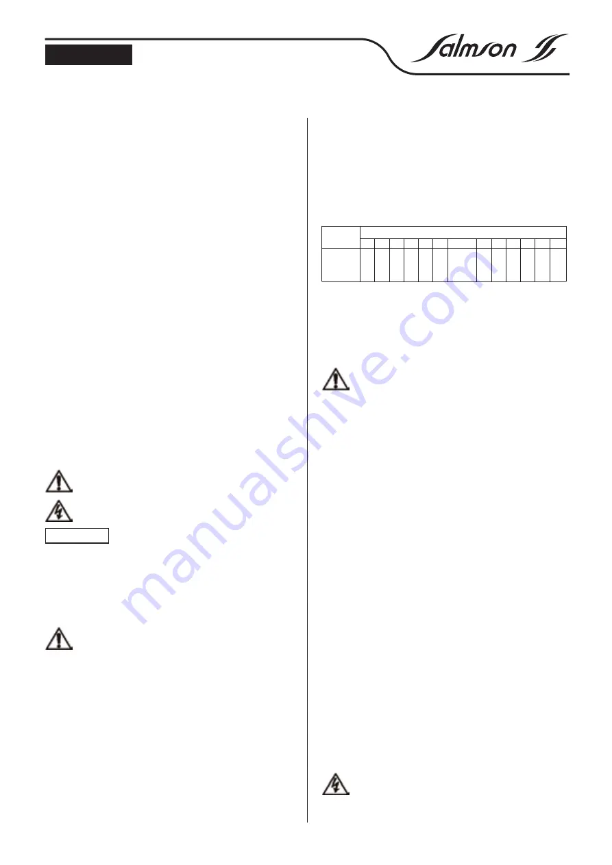
Outline dimensions (see Fig. 2)
4.3 Accessories
5. INSTALLATION
5.1 Installation
Install only after finishing all welding and brazing work and
thoroughly cleaning the pipes. Dirt can interfere with the pro-
per operation of the pump.
- Install the pump in a dry place protected from frost.
- The installation surface must be level and flat: any tilting of the
pump would cause premature bearing wear.
- Place the pump where it will be easy to reach, to facilitate inspec-
tion and removal work. The pump must always be installed per-
fectly upright on a sufficiently heavy concrete base.
- The installation and connection dimensions are given in the table
above (outline dimensions) and in figure 2.
- For especially heavy pumps, place a hook or a ring of sufficient
capacity (total weight of pump) to allow the use of a hoist or simi-
lar device for the servicing and repair of the pump.
- When fitting the oval flange, only the screws supplied should be
used. The use of longer screws might damage the base of the
pump.
- The arrow on the pump casing indicates the direction of flow.
- Take care to install the suction and discharge pipes so as not to
exert any stress. The pipes must be attached so that the pump
does not bear their weight.
- In principle, there should be isolating valves before and after the
pump, making it unnecessary to empty and refill the whole instal-
lation to check or replace the pump.
- As regards the nominal cross-section of the suction pipe, we
recommend a cross-section at least as large as that of the pump
coupling.
- To avoid any loss of head, use the shortest possible suction pipe
and keep it free of bends that would narrow the passage.
- A check valve should be placed on the discharge pipe.
- For direct connection to a public drinking water system, the suc-
tion pipe must also have a check valve and a guard valve.
- For indirect connection via a tank, the suction pipe must have a
strainer, to keep any impurities out of the pump.
5.2 Electrical connections
The electrical connections and checks should be made by a
qualified electrician and comply with the standards in force.
Type
Dimensions (mm)
A
B
C
D
E
F
H
K
L
R
S
T
U
202-210
100 180 157 212 204 50 354-596 20 160 R1
75 12 M10
402-410
100 180 157 212 204 50 354-596 20 160 R1
1/4
75 12 M10
802-806
130 215 187 252 258 80 425-575 20 200 R1
1/2
100 12 M12
ENGLISH


