background image

7

RIS 2500PE/PW EKO 3.0

www.salda.lt

[ it ]

[ ru ]

[ en ]

[ de ]

- Maintenance and repair should only be per-

formed by experienced and trained staff.

- The  fan  should  be  inspected  and  cleaned  if 

needed at least 1/year.

- Be sure the fan is disconnected from power 

source  before  performing  any  maintenance 

or repair.

- Proceed to maintenance and repair after any 

rotation in the fan stopped.

- Observe staff safety regulations during main-

tenance and repair.

- The motor is of heavy duty ball bearing con-

struction. The motor is completely sealed and 

requires no lubrication for the life of the motor.

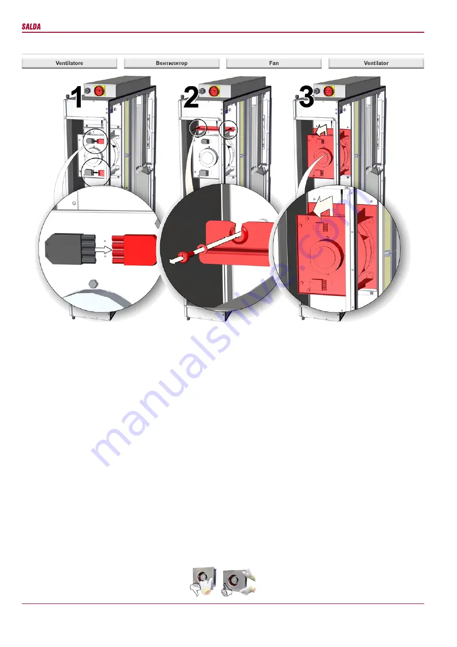
- Detach fan from the unit.

- Impeller should be specially checked for buil-up 

material or dirt which may cause an imbalance.  

Excessive  imbalance  can  lead  to  accelerated 

wear on motor bearings and vibration.

-  Clean  impeller  and  inside  housing  with  mild 

detergent, water and damp, soft cloth.

- Do not use high pressure cleaner, abrasives, 

sharp instruments or caustic solvents that may 

scratch or damage housing and impeller.

- Do not plunge impeller into any fluid.

-  Make  sure,  that  impeller’s  balance  weights 

are not moved.

- Make sure the impeller is not hindered.

- Mount the fan back into the unit. Connect the 

fan to power supply source.

- If the fan does not start after maintenance or 

repair, contact the manufacturer.

- Montage und Elektroarbeiten nur durch aus-

gebildetes  und  eingewiesenes  Fachpersonal 

und nach den jeweils zutreffenden Vorschriften 

ausführen. 

- Die Anlage muss min. einmal pro Jahr geprüft 

und gereinigt werden.

- Vor der Wartung oder Reparatur sicherstellen, 

dass die Anlage vom Stromnetz getrennt ist.

- Arbeiten dürfen nur bei abgeschaltetem und 

mechanischem Stillstand des Laufrades sowie 

nach Abkühlung  der  Heizung  vorgenommen 

werden! Gegen Wiedereinschalten sichern! 

- Arbeitssicherheitsregelungen bei der tech-

nischen Bedienung beachten. 

- In der Motorkonstruktion sind hochwertige 

Lager eingebaut. Die Lager sind eingepresst 

und erfordern keine Schmierung. 

- Ventilator von der Anlage abschalten.

- Die Flügel vom Ventilator auf Ablagerungen 

und Staub prüfen, starke Verschmutzung kann 

zu  Unwucht  führen.  Die  Unwucht  verursacht 

eine Vibration und schnelleren Lagerverschleiß.

- Flügel und Gehäuse mit einem sanften Rei-

nigungsmittel  abwaschen,  keine  aggressiven 

Putzmittel verwenden die das Material angreifen 

könnten. Flügel und Gehäuse danach mit viel 

Wasser  gründlich  reinigen,  keine  Hochdruck-

anlage,  Putzmittel,  scharfes  Werkzeug  oder 

aggressive  Stoffe  verwenden,  die  zu  Kratzer 

und Beschädigungen führen könnten.

- Beim Reinigen der Flügel Motor vor Feuch-

tigkeit und Nässe schützen.

-  Prüfen,  dass  die  Wuchtgewichte  am  Flügel 

nicht verschoben werden.

- Flügel darf nicht am Gehäuse streifen.

-    Montieren  des  Ventilators  wieder  in 

der  Anlage.  Anschließen  der  Anlage  ans 

Stromnetz.

-  Sollte  sich  nach  Wartung  der Anlage  der 

Ventilator  nicht  mehr  einschalten  lassen  oder 

der  Thermokontaktschutz  auslösen,  an  den 

Hersteller wenden.

-  Работы  по  обслуживанию  должны  прово-

диться только опытными и квалифицирован-

ными специалистами.

- Осмотр и работы по обслуживанию долж-

ны проводиться не реже 1 раза в 6 месяцев.

- Сооблюдайте правила техники безопасно-

сти  проводя  работы  по  обслуживанию  или 

ремонту.

- Перед началом работ по обслуживанию или 

ремонту  убедитесь,  что  вентилятор  отклю-

чен от питания.

-  Приступайте  к  работам  по  обслуживанию 

или ремонту только убедившись, что в вен-

тиляторе  остановилось  любое  механиче-

ское движение.

- Подшипники запрессованы не требуют об-

служивания на весь срок службы двигателя.

- Отсоедините вентилятор от агрегата.

- Тщательно осмотрите крыльчатку вентиля-

тора.  Покрытие  пылью  или  пр.  материала-

ми может нарушить балансировку крылчат-

ки. Это вызывает вибрацию и ускоряет износ 

подшипников двигателя.

-  Крыльчатку  следует  чистить  не  агрессив-

ными, коррозию крылчатки и корпуса не вы-

зывающими моющими средствами и водой.

- Для чистки крыльчатки запрещаетса исполь-

зовать струю высокого давления, абразивные 

материалы, острые предметы и агрессивные 

расстворители,  способные  поцарапать  или 

повредить крыльчатку вентилятора.

- Во время чистки не погружайте крыльчат-

ку в жидкость.

-  Убедитесь,  что  балансировочные  грузики 

крылчатки на своих местах.

-  Убедитесь,  что  крылчатка  не  прикосает-

са к корпусу.

- Установите вентилятор обратно в агрегат и 

подключите к электросети.

- Если обратно установленный вентилятор не 

включается или срабатывает термоконтакт-

ная защита - обращайтесь к производителю.

- Solo personale esperto e qualificato può ef-

fettuare lavori di manutenzione straordinaria.

- Il ventilatore deve essere ispezionato visiva-

mente e pulito almeno una volta all’anno.

- Prima di effettuare i lavori di manutenzione e 

di riparazione assicurarsi che il dispositivo sia 

scollegato dalla rete elettrica.

- Effettuare i lavori di manutenzione solo quan-

do tutte le parti del ventilatore si sono fermate.

- Durante i lavori di manutenzione tecnica, at-

tenersi alle opportune disposizioni di sicurezza 

sul lavoro.

- Nel corpo del motore sono inseriti i cuscinetti 

ad altre efficienza. Sono sigillati e non richiedo-

no alcuna lubrificazione per tutta la durata della 

vita del motore.

- Scollegare il ventilatore dall’unità. 

-  È  necessario  ispezionare  accuratamente  la 

girante  del  ventilatore,  controllando  che  non 

si sia accumulata polvere o altre sostanze che 

potrebbero sbilanciare la ventola. Lo sbilancia-

mento provoca vibrazioni e accelera l’usura dei 

cuscinetti del motore.

- Pulire la ventola e la parte interna del corpo 

con acqua e detergente delicato non corrosivo.

- Per pulire la ventola non utilizzare apparecchi 

ad  altapressione,  prodotti  abrasivi,  strumen-

ti  appuntiti  e  solventi  aggressivi  che  possono 

graffiare o danneggiare la ventola.

- Durante la pulizia della ventola non immerge-

re motore nell’acqua.

- Assicurarsi che i pesi di bilanciamento della 

ventola siano nella loro sede.

- Assicurarsi che la ventola non sfreghi contro 

il corpo dell’unità.

- Reinserire il ventilatore nel dispositivo. Colle-

gare alla rete elettrica.

- Se dopo la manutenzione il ventilatore non si 

accende oppure la protezione termica entra in 

azione, contattare il produttore.

Summary of Contents for RIS 2500PE 4.5 EKO 3.0

Page 1: ...portare modifiche ai dati tecnici del prodotto senza preavviso RIS 2500PE PW EKO 3 0_P0026_AP_0002 CENTRALE DI VENTILAZIONE CON RECUPERO DI CALORE AHU WITH HEAT RECOVERY L FTUNGSGER TE MIT W RMER CKGE...

Page 2: ...ettrica dell unit HVAC 21 Guida per la riparazione del sistema 22 Guasti principali dell unit HVAC e soluzioni per eliminarli 24 Scheda di controllo RG1 27 Significato dei LED 28 Designazione convenzi...

Page 3: ...EKO 3 0 35 Product maintenance table 36 DE Inhalt Transport und Lagerung 4 Beschreibung 4 Schutzmassnahmen 4 Bestandeile des Ger tes 5 Betriebsbedingungen 5 Bedienung 6 Filter 6 Ventilator 6 W rmetaus...

Page 4: ...connection boxes air intake or discharge flanges Avoid hits and shock overloads Before installation units must be stored in a dry room with the relative air humidity not exceeding 70 at 20 C and with...

Page 5: ...la condotta dell aria connessa Nel caso in cui un oggetto estraneo dovesse entrare nel dispositivo scollegare immediatamente il dispositivo dalla fonte di alimentazione Prima di estrarre l oggetto est...

Page 6: ...t Mischung von Glykol und Wasser bef llt Der Hersteller bernimmt keine Gew hrleis tung die im Folge der Nichtbeachtung oben genannten Anweisungen und daraus resul tierenden Einrichtungsbesch digungen...

Page 7: ...einem sanften Rei nigungsmittel abwaschen keine aggressiven Putzmittel verwenden die das Material angreifen k nnten Fl gel und Geh use danach mit viel Wasser gr ndlich reinigen keine Hochdruck anlage...

Page 8: ...nd the fans stop rotat ing After identifying and removing the reason of failure to start the unit press the reset button The failure can be identified only by a qualified professional If necessary the...

Page 9: ...tra zione exhaust abluft potenza corrente power current Nennleistung Nennstrom kW A 0 675 3 0 giri speed Drehzahl min 1 2800 di immis sione supply zuluft potenza corrente power current Nennleistung Ne...

Page 10: ...557 5 625 7 1992 715 105 400 145 188 700 145 700 261 44 499 RIS 2500PE PW EKO 3 0 Classe e dimensioni dei filtri Filter class and dimen sions Filterklasse und Abmes sungen Di immissione exhaust abluf...

Page 11: ...easily disassembled and the heater could be removed from the unit casing when performing service or repair works Pipes with supply and return heat carriers must be connected in such way that the heat...

Page 12: ...densates 2 mit 0 3 Grad niedriger als die andere Seitenwand steht Die Seitenwand des WRG Ger tes 1 mit demAus lassrohr des Kondensates darf nicht h her als die andere Seitenwand stehen Dann die Rohre...

Page 13: ...e draining system should be isolated with thermal isolation or heating installed The siphon 3 must be mounted below the AHU 1 level menschlie en Die Rohre 4 sollten mindestens mit einem Winkel von 3 G...

Page 14: ...automatic controll system TE temp sensor for exhaust air DTJ temp and humidity sensor for extract air PS1 Supply air differential pressure switch PS2 Extract air differential pressure switch PS3 Heat...

Page 15: ...e Ventil AKS3 Silenziatore per canale circolare Funnel trap for a dripping con densate Sifon f r Kondensat WP Pompa di scarico condensa Water pump Wasserpumpe SVS 700x400 RIS 2500PW EKO 3 0 Batteria a...

Page 16: ...Pa 0 100 0 720Pa 0 60 TJ T1 TV VV 2 M4 M5 24VAC 3 M6 Esempio Example Exempel La temperatura dell aria di mandata pu es sere regolata in base alla temperatura misurata dal sensore dell aria immessa e a...

Page 17: ...wird die BOOST Funktion dargestellt Die BOOST Funktion ist nicht aktiv wenn der W rmetauscherschutz angelaufen ist Im Pult FLEX kann die Arbeitsdauer der gew nschten Funktion gew hlt werden nachdem da...

Page 18: ...i ventilazio ne vd paragrafo II 6 3 della Flex in base all aria di mandata Supply in base all aria estratta Room ventilazione automatica By Outdoor In modalit di ventilazione in base all ariaimmessa l...

Page 19: ...lbst wiederhergestellt und muss vom Pult wiederhergestellt neu gestartet werden b Wenn die Anlage einen elektrischen Heizer hat hat sie zwei Schutzstufen gegen die ber hitze Elektrischer Heizer ist ge...

Page 20: ...funktion des Plattenw rmetauschers 1 active o passive F i g 4 4 F i g 4 Abb 4 Microselettori 1 e 2 1 2 Microswitches 1 and 2 Mikroschalter 1 und 2 3 RS485_1 RS485_2 RS485_1 RS485_2 Modbus Stouch RS485...

Page 21: ...mperatursensors 1 active o passive 11 ToutDoor 01h_Read_Coils 11 1 it Allarme sensore della temperatura dell aria esterna l unit di controllo continua a funzionare stabilendo ToutDoor 0C ru ToutDoor 0...

Page 22: ...t werden Steuerpult muss auf dem vorgesehenen Platz montiert werden Anschlusskabel Flex der ein Teil der Aus r stung ist muss zwischen dem Steuerpult und dem HKLK Aggregat gelegt werden Empfehlenswert...

Page 23: ...transmitter Jumper STOP NO START NC BOOST CO2 Extract air pressure Air quality transmitter Supply air pressure Transmitter 2 26 24V DC 27 intput 0 10V DC 28 GND X16 10 28 27 U P 26 27 28 26 24 25 23...

Page 24: ...ch tzt richtig montiert werden Temperaturf hler f r Frostschutz TV muss mit einem B gel auf dem Rohr des R ck wasserheizers befestigt werden Kapillarf hler des Frostschutzthermostats T1 muss hinter de...

Page 25: ...315 mA pr fen Guasto dei connettori elettrici del dis positivo Possible unit fauit at electrical connections of the unit St rung in elektrischen Verbindungen Anschl ssen des Aggregats it Verificare pr...

Page 26: ...ienpuit oder RG1 Regler auszutauschen Il i ventilatore ventilatori non funziona non funzionano Fan s not working Ventilator en nicht funktioniert Guasto del ventilatore dell aria immessa PV o quella e...

Page 27: ...termostato Se la temperatura dell aria di mandata bassa controllare la centrale termica ru 1a 4 1 2a en Switch off the supply voltage Disconnect the respective sensor plug from the automation Measure...

Page 28: ...28 RIS 2500PE PW EKO 3 0 www salda lt it ru en de...

Page 29: ...elettrica rotore Electric preheater rotor ON OFF 230V 50Hz Elektrovorheizer Rotor EIN AUS 230V 50Hz O 16A 100 X12 Tensione del ventilatore alla velocit attuale Voltage of Normal speed for air fans Sp...

Page 30: ...lers X33 3 VAL Apertura della valvola della batteria PWM 24v 50hz PWM 24v 50hz Cooling valve opening PWM 24v 50hz ffnen der K hlungsklappe PWM 24v 50hz AO X33 4 VAL Chiusura della valvola della batter...

Page 31: ...rischen Luft der Au enluft X33 21 T OUT Sensore esterno Outdoor sensor Au ensensor AI X33 22 COM COM X33 23 T SET Entrata del segnale del ventilatore dell aria estratta 0 10V dal trasmettitore i di CO...

Page 32: ...reclamo al vettore Non ci assumiamo alcuna responsabil it per i danni di questo tipo La presente garanzia non copre i guasti provocati da incidenti o eventi accidentali da uso improprio manutenzione i...

Page 33: ...N L3 L2 L1 PE N L1 L2 L2 L1 N PE L1 L2 L3 N PE 1 2 3 4 5 6 7 8 9 9 8 7 6 5 4 3 2 1 X4 X3 0 10V in GND IV L N PE PE N L PE N L NC COM PV GND 0 10V in X31 L Q1 Main Switch 3P PE PE N N Conntacts 2 1 X3...

Page 34: ...5 X34 X32 1 2 Conntacts N N PE PE Q1 Main Switch 3P L X31 0 10V in GND PV COM NC L N PE L N PE PE N L IV GND 0 10V in X3 X4 1 2 3 4 5 6 7 8 9 9 8 7 6 5 4 3 2 1 PE N L3 L2 L1 PE N L1 L2 L2 L1 N PE L1 L...

Page 35: ...X22 1 9 PE N L3 L2 L1 PE N L1 L2 L2 L1 N PE L1 L2 L3 N PE 1 2 3 4 5 6 7 8 9 9 8 7 6 5 4 3 2 1 X4 X3 0 10V in GND IV L N PE PE N L PE N L NC COM PV GND 0 10V in X31 L Q1 Main Switch 3P PE PE N N Connt...

Page 36: ...7 4 X37 3 V2 COM X37 1 X37 2 COM V1 AC N PUMP A4 A4 RH 2 1 PS3 X16 2 15 16 11 10 4 1 TV T1 29 30 31 N L PE 1f 230V AC X16 7 M4 1A F2 32 X16 8 33 34 24VDC 0 10VDC G Y 0 M6 0 GND Y 0 10V G 24VDC W1 X16...

Page 37: ...37 RIS 2500PE PW EKO 3 0 www salda lt it ru en de...

Page 38: ...tuzione dei filtri Filter replacement Filterwechsel Ogni 3 4 mesi 3 4 Every 3 4 months Alle 3 4 Monate NOTA L acquirente del prodotto ha l obbligo di compilare la Tabella di manutenzione del prodotto...

Reviews: